Ultra-high-efficiency engines and corresponding thermodynamic system

a thermodynamic system and ultra-high-efficiency technology, applied in the direction of machines/engines, efficient propulsion technologies, mechanical apparatuses, etc., can solve the problems of approximately two-thirds of the input heat being wasted and the thermodynamic loop remains wide open, and achieve the effect of improving the thermodynamic efficiency of a number of engines

Active Publication Date: 2011-10-20
BURKHART TECH
View PDF13 Cites 53 Cited by
  • Summary
  • Abstract
  • Description
  • Claims
  • Application Information

AI Technical Summary

Benefits of technology

[0008]The present invention relates to greatly improving the thermodynamic efficiency of a number of engines, power plants, and other thermodynamic systems. Efficiencies of greater than 50 percent up to approximately 85 or 90 percent may be achieved. This is accomplished by the addition of a heat pump cycle that pumps at least a portion of the traditionally large amount of waste heat back to another portion of the cycle, such as to a low or intermediate temperature level in the power cycle, instead of dumping this heat to a reservoir or sump. Hence, instead of wasting up to two-thirds of the input heat, most of it ends up being recycled.
[0014]The system may be an air-breathing engine having a fuel combustor and fuel and air intakes to the combustor. The air-breathing engine may be a jet engine having a nozzle connected with the fuel combustor and the thermal input may remove heat from the nozzle. The heat pump may include a turbine which drives an air compressor supplying air to the fuel combustor. The air may be compressed to a liquid state prior to being supplied to the fuel combustor. The system may be a bottoming cycle for improving efficiency of the engine with the thermal input receiving waste heat produced by the engine. The heat pump may include an evaporator and condenser. The evaporator receives heat at one portion of the working fluid and the condenser delivers heat at or near the thermal input. The working fluid may include a liquid and a heat exchanger between the working fluid and the evaporator in another heat exchanger between the working fluid and the condenser. The air-breathing engine may be a vehicle engine, such as an aircraft engine or a land-based vehicle engine.

Problems solved by technology

However, the thermal loop remains wide open with approximately two-thirds of the input heat being wasted between points #5 and #1.

Method used


Image

  • Ultra-high-efficiency engines and corresponding thermodynamic system
  • Ultra-high-efficiency engines and corresponding thermodynamic system
  • Ultra-high-efficiency engines and corresponding thermodynamic system

Examples


Embodiment Construction

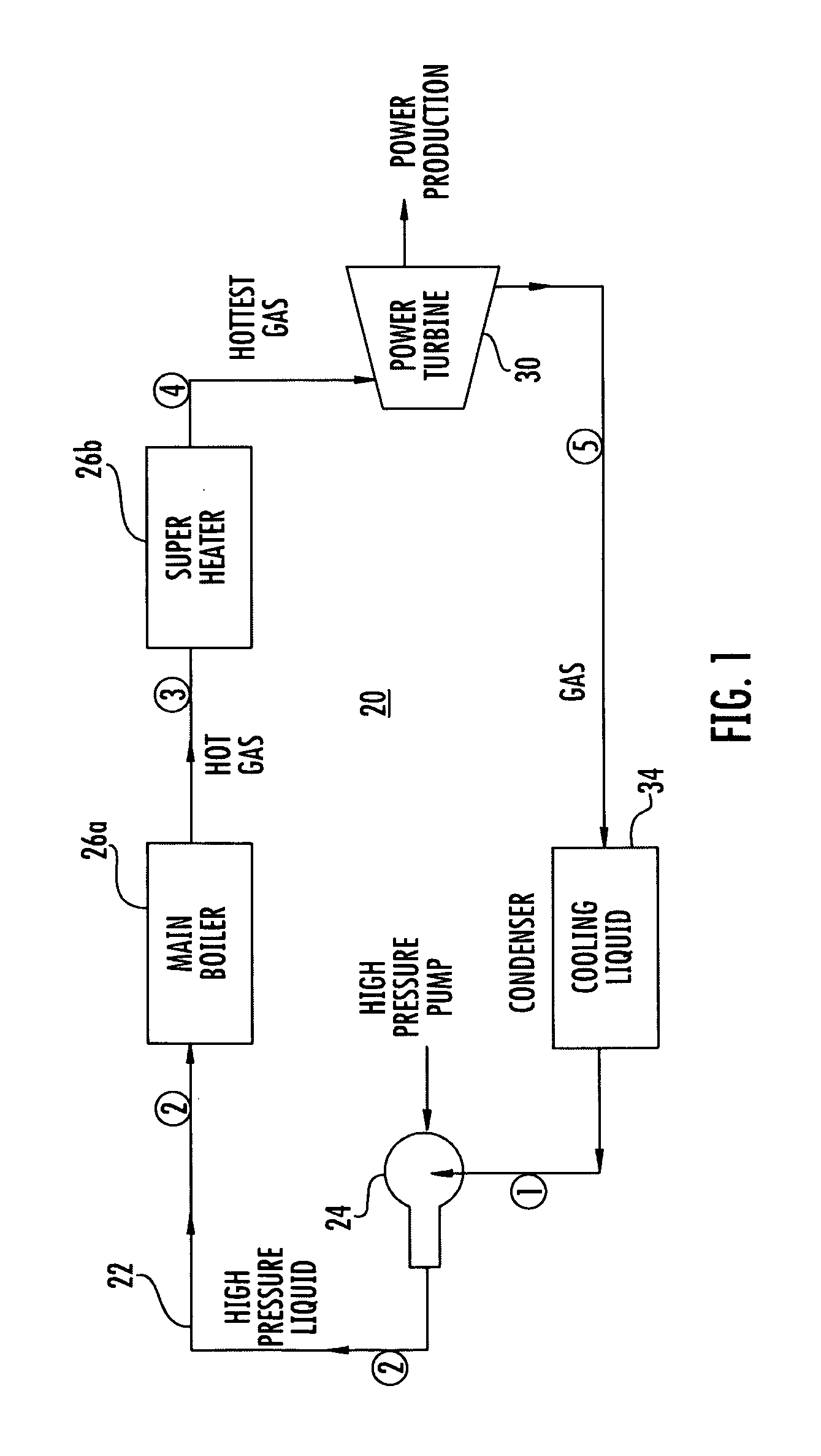
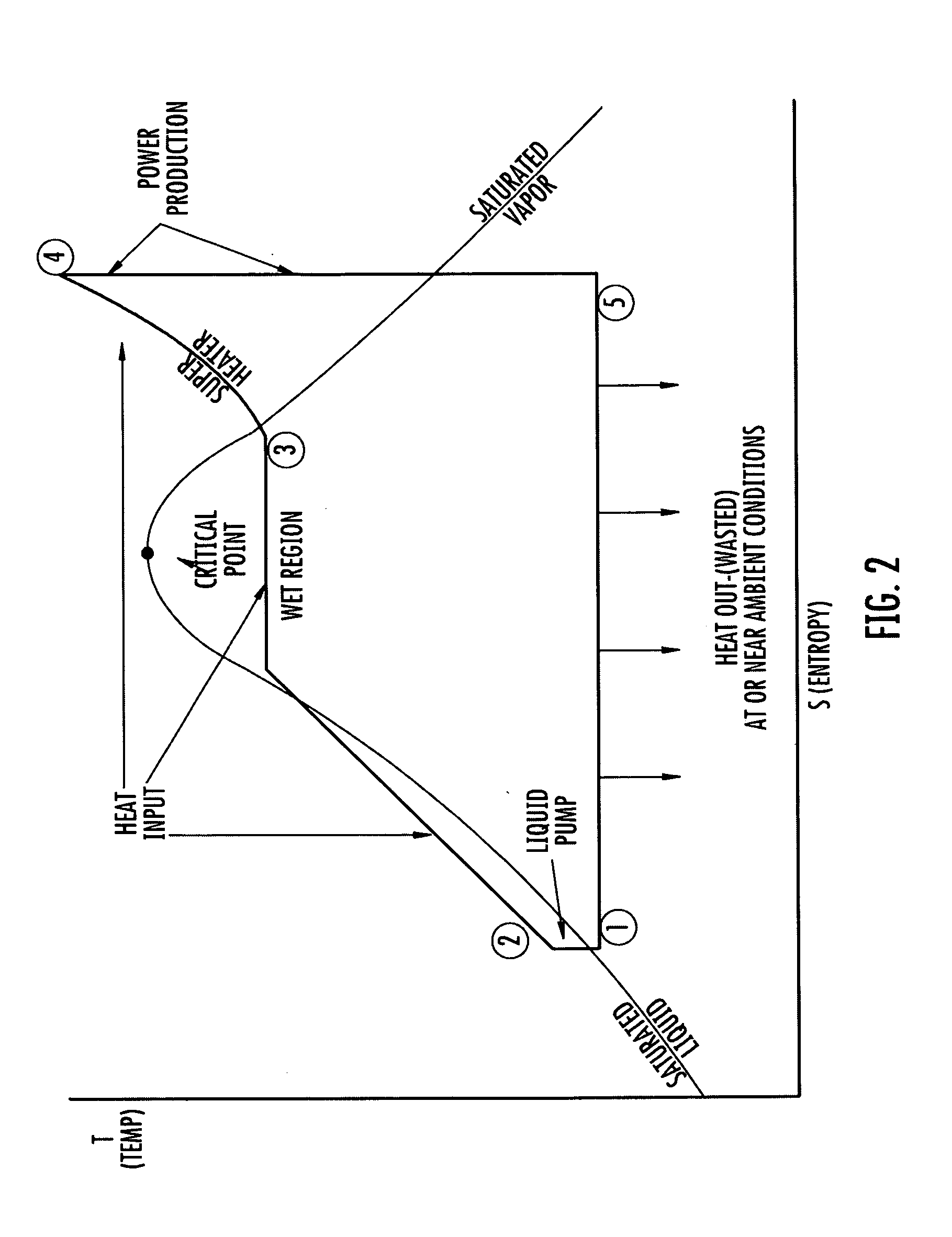
[0061]Referring now to the drawings and the illustrative embodiments depicted therein, the preferred embodiment utilizes a modified Carnot cycle (FIGS. 3 and 4). Compression is illustrated as kept to a minimum so as to minimize both the compression power and the temperature differential across the compression. This results in the sloping heat input part of the cycle. The vertically straight line, nearly an isentropic line, represents the work produced, such as through an expansion device. The bottom horizontal line represents the large heat rejection of the power cycle, which does not need to be discharged to an external heat reservoir or sump. At least a portion of the rejection heat is pumped over to the slanted heat input line, such as by a heat pump as illustrated in FIG. 4.

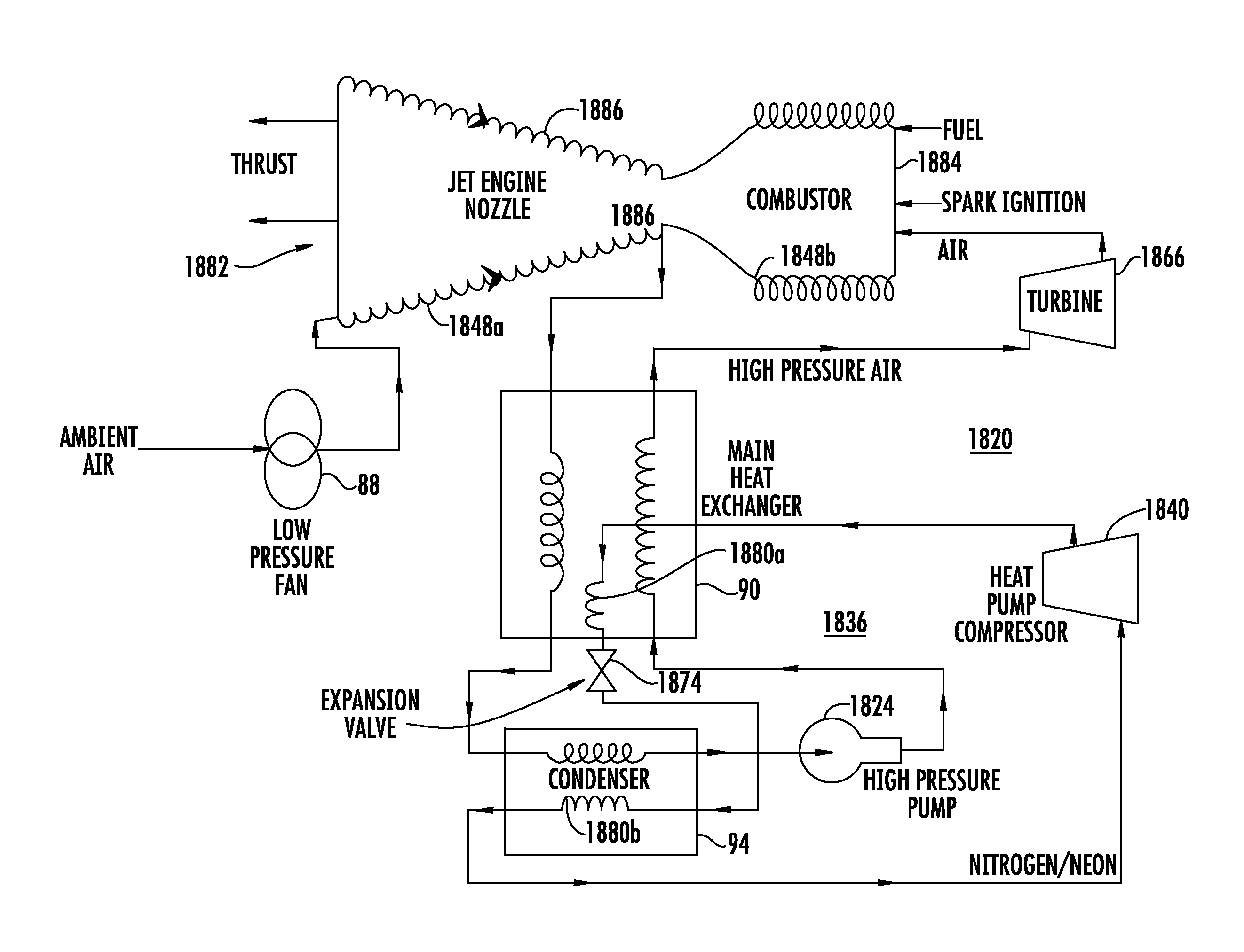
[0062]The basic cycle employs a heat pump 136 to transfer heat from one portion, such as the low temperature side of an engine, or other thermodynamic system, to another portion, such as the high temperature ...


PUM


Abstract

A thermodynamic system and method of producing useful work includes providing a working fluid and a fluid pump, or compressor, for pumping the working fluid in a cycle. A thermal input is provided for supplying heat to the working fluid. An expansion device downstream of the thermal input converts motion of the working fluid to useful work. A heat pump is provided. A number of different means of implementing the heat pump are presented, including direct transfer of working fluid mass flow. The heat pump pumps heat from one portion of the working fluid to another portion of the working fluid. For some applications, a regenerator, or recuperator, may be used to transfer heat from a high temperature portion of the working fluid to a lower temperature portion.

Description

CROSS REFERENCE TO RELATED APPLICATIONS[0001]This application is a continuation-in-part of International Patent Application No. PCT / US09 / 61210, filed on Oct. 20, 2009, which claims priority from U.S. provisional patent application Ser. No. 61 / 106,823, filed on Oct. 20, 2008, and U.S. provisional patent application Ser. No. 61 / 227,597, filed on Jul. 22, 2009; and this application claims, priority from U.S. provisional patent application Ser. No. 61 / 434,179, filed on Jan. 19, 2011, the disclosures of which are hereby incorporated herein by reference in their entireties.BACKGROUND OF THE INVENTION[0002]The present invention is directed to a thermodynamic system and a method of producing work and, in particular, to such system and method having efficiency enhancing techniques.[0003]Engine-efficiency is traditionally defined as the percentage of useful work produced by an engine divided by the heat input to the engine. In the case of complex power plants, jet engines, gasoline engines, d...

Claims


Application Information

Patent Timeline
Patent Type & Authority Applications(United States)
IPC IPC(8): F03G7/00F01K27/00
CPCF01K27/00F01K27/02F02C7/143Y02E10/34F03G7/05Y02T50/671Y02T50/675F03G7/04Y02T50/60
Inventor BURKHART, JAMES A.
Owner BURKHART TECH
Why Eureka
Try Eureka