Electrical Damping for Isolation and Control of Mems Sensors Experiencing High-G Launch

a technology of electric damping and high-g launch, which is applied in the direction of speed/acceleration/shock measurement, instruments, surveying and navigation, etc., can solve problems such as changing sensor performance, and achieve the effect of dampening the motion of flexurally suspended structures and minimizing sensor displacemen

Inactive Publication Date: 2011-10-20
MILLI SENSOR & ACTUATOR SYST
View PDF0 Cites 19 Cited by
  • Summary
  • Abstract
  • Description
  • Claims
  • Application Information

AI Technical Summary

Benefits of technology

[0005]This invention relates to the survivability of MEMS gyroscope and accelerometer sensors used in high-G situations such as in the gun launching of munitions and the preservation of the sensor operational properties so the sensors operate as well after launch. The field is gun—hardening of inertial sensors. High-G acceleration in this case is in the form of an acceleration pulse or shock over a short period of time. The impact on the sensors is to cause excessive deflection resulting in breakage or deformation that changes sensor performance. This invention introduces an active means to minimize the sensor displacement so that the sensor structures do not exceed their elastic limit. Staying within the elastic limit is necessary to retain the operational properties of the sensors. The field is also about controlling the post-shock condition of “ringing”, which is oscillations of the sensors at the natural frequencies of its structure. Operation of the sensors requires that the settling time over which the ringing occurs is made as small as possible. The solution is to dampen the motion of the flexurally suspended structures of the sensor using electrical energy that is applied through capacitive components of the designs to create motion-controlling forces. By critically damping the motion, the ringing will not occur.

Problems solved by technology

The impact on the sensors is to cause excessive deflection resulting in breakage or deformation that changes sensor performance.

Method used


Image

  • Electrical Damping for Isolation and Control of Mems Sensors Experiencing High-G Launch
  • Electrical Damping for Isolation and Control of Mems Sensors Experiencing High-G Launch
  • Electrical Damping for Isolation and Control of Mems Sensors Experiencing High-G Launch

Examples


Embodiment Construction

Introduction

[0032]The invention is described with respect to linear accelerometer and simple Coriolis gyro designs. However, this is not a limitation of the invention as the invention can apply to any MEMS sensor that has one or more flexurally suspended structures that need to be controlled.

Linear Accelerometer

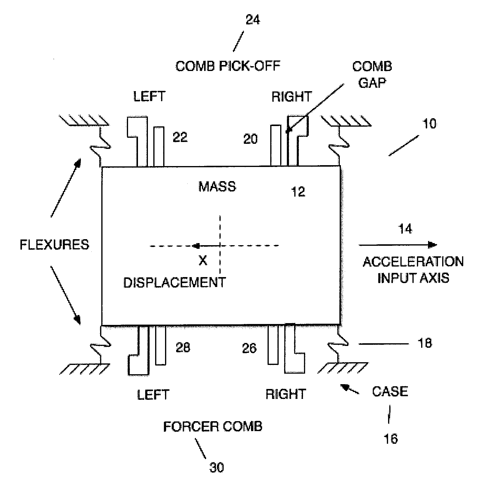
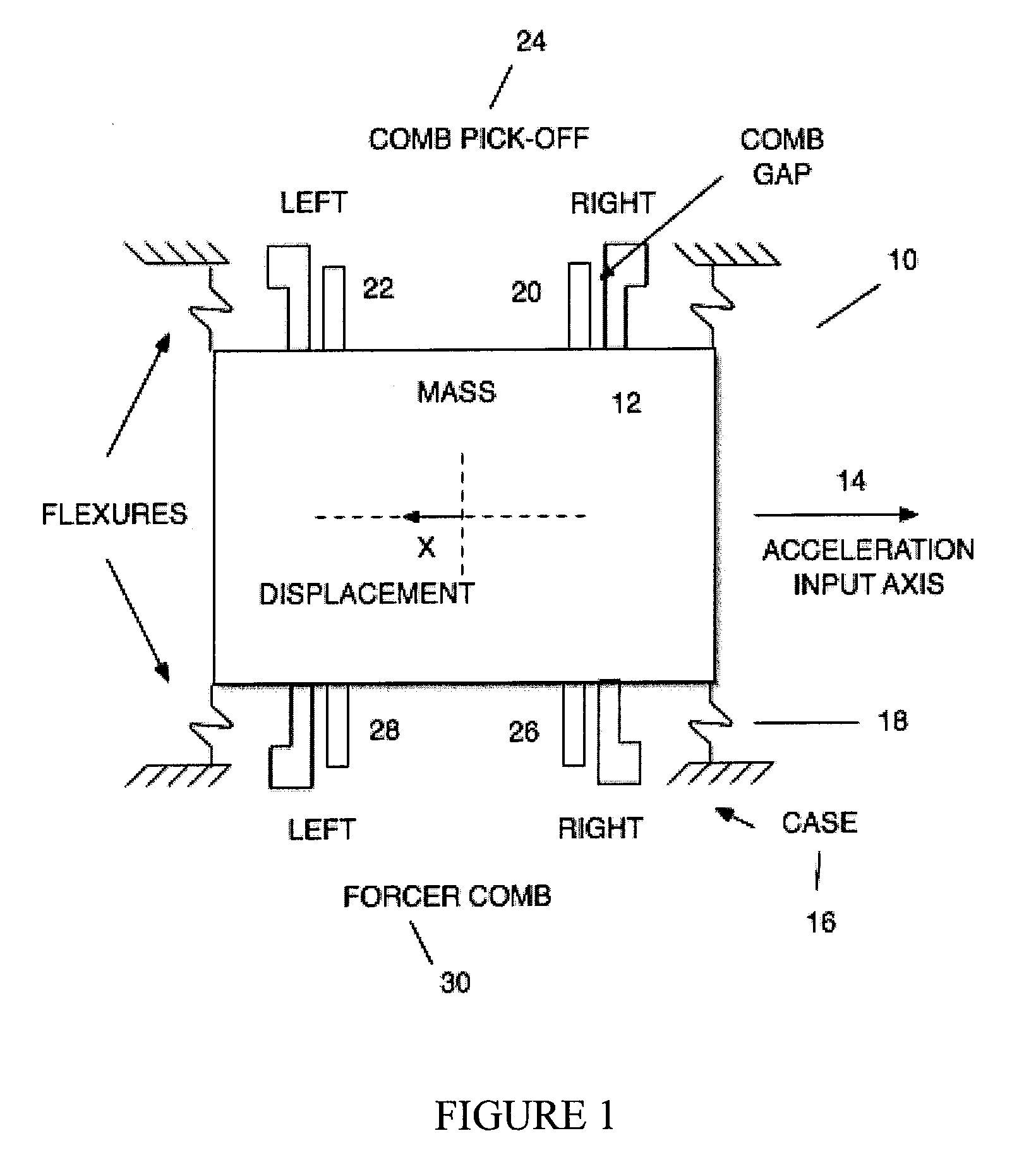
[0033]The conceptual linear accelerometer 10 is shown in FIG. 1; the design of the accelerometer per se is known in the art. It is a spring mass design comprising a mass 12 that is reactive to acceleration along an Acceleration Input Axis 14. The mass, also known as a proof mass, is flexurally attached to a fixed portion of the sensor (in this example, case 16) with four bending flexures 18 that allow displacement, X, of the mass along the Acceleration Input Axis. Note the displacement response is in the opposite direction from the acceleration input direction. A set of comb fingers comprising a Right comb finger pair 20 and a Left comb finger pair 22 makes up the pick-off co...


PUM


Abstract

A system and method for damping undesired motion of a suspended structure that is connected by one or more flexures that have an elastic limit to a fixed structure in a MEMS sensor, wherein the undesired motion is caused by a high G acceleration pulse. At one or more of before and during a high G acceleration pulse that could move the suspended structure beyond the elastic limit of a flexure, the system actively generates an attractive force that acts to counteract motion of the suspended structure caused by the high G acceleration pulse, so as to maintain motion of the suspended structure within the elastic limit of the flexure.

Description

CROSS-REFERENCE TO RELATED APPLICATION[0001]This application claims priority of Provisional Patent Application Ser. No. 61 / 325,048 filed on Apr. 16, 2010. The contents of this Provisional Patent Application are incorporated herein by reference.FIELD OF THE INVENTION[0002]This invention relates to the survivability of MEMS gyroscope and accelerometer sensors used in high-G situations such as in the gun launching of munitions and the preservation of the sensor operational properties so the sensors operate as well after launch.BACKGROUND OF THE INVENTION[0003]In order for MEMS gyroscope and accelerometer sensors to guide a munition it is not sufficient for them to just survive the firing shock; the sensors must in addition be maintained in a state of low stress during the shock so that upon exiting the launch barrel, the sensors will operate as designed and tested. Usefulness upon exiting also means that the settling time for any ringing caused by residual shock input needs to be contr...

Claims


Application Information

Patent Timeline
Patent Type & Authority Applications(United States)
IPC IPC(8): G01P15/125
CPCF16F15/03G01C19/5776G01P2015/0882G01P2015/0814G01P15/125
Inventor CARDARELLI, DONATO
Owner MILLI SENSOR & ACTUATOR SYST
Why Eureka
Try Eureka