
Lift assist mechanism

a technology of lifting assist and auxiliary mechanism, which is applied in the direction of shock absorbers, wing accessories, manufacturing tools, etc., can solve the problems that the simple assist mechanism cannot be completely suitable for extremely heavy loads, and the simple assist mechanism cannot be assimilated

Inactive Publication Date: 2011-10-20
BE INTPROP
View PDF7 Cites 28 Cited by
  • Summary
  • Abstract
  • Description
  • Claims
  • Application Information

AI Technical Summary

Benefits of technology

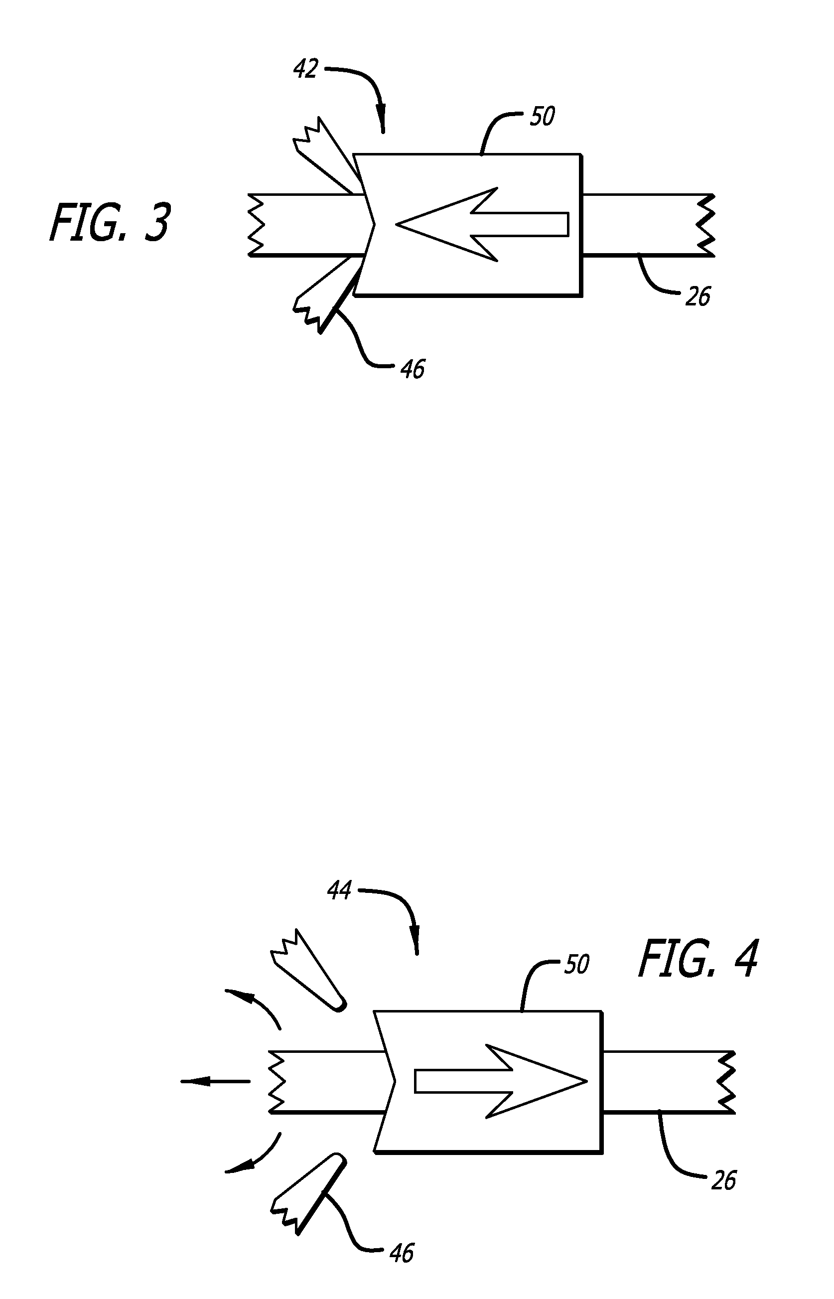
[0008]In another presently preferred aspect, the spring lock includes a locking pawl configured to releasably engage the spring shaft, a solenoid connected to the locking pawl to cause the locking pawl to latch and restrain movement of the spring shaft when a lift assist of the movable component is not required, and to cause the locking pawl to unlatch and release the spring shaft for movement of the spring shaft when the lift assist is required. A spring shaft collar is disposed on the spring shaft, and is loaded against the locking pawl engaged with the spring shaft to prevent the solenoid from unlatching the mechanism when the movable component is in the raised position and a lift assist of the movable component is not required. The spring shaft collar is pushed away from the locking pawl by the lift assist spring when the movable component is in the lowered position and a lift assist of the movable component is required, allowing the locking pawl to be disengaged from the spring shaft by the solenoid. In another presently preferred aspect, when the movable component is a stowage bin portion cooperatively connected to a stationary bin support structure for movement of the stowage bin portion between lowered and raised positions relative to the stationary support structure, a switch with an electrical connection to receive electrical power from an aircraft electrical system is provided for operation of the solenoid.

Problems solved by technology

Simple assist mechanisms can also be ill suited to assisting with heavy loads, and can be totally unsuitable for extremely heavy loads.

Method used


Image

  • Lift assist mechanism
  • Lift assist mechanism
  • Lift assist mechanism

Examples


Embodiment Construction

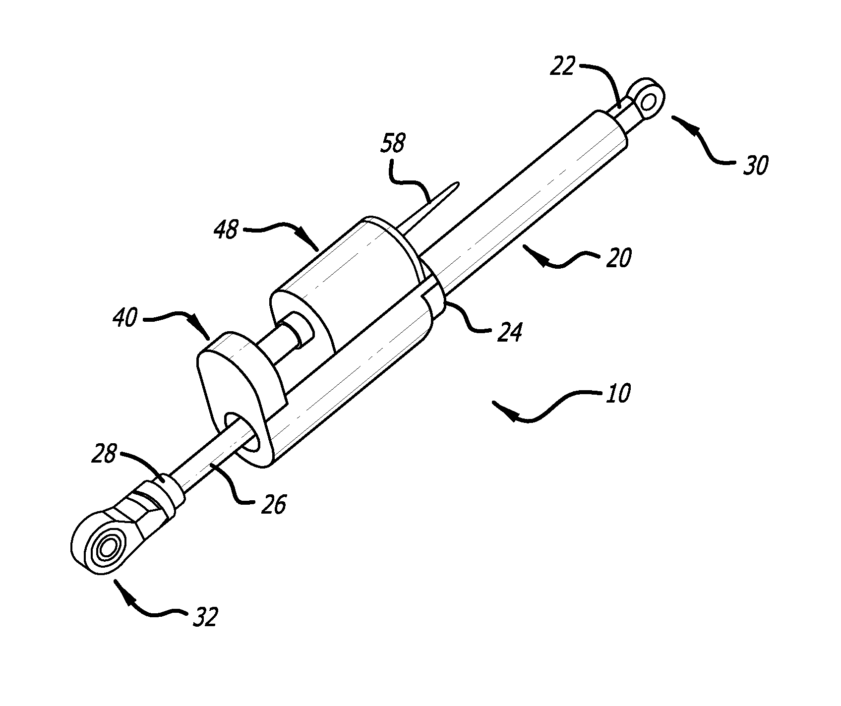
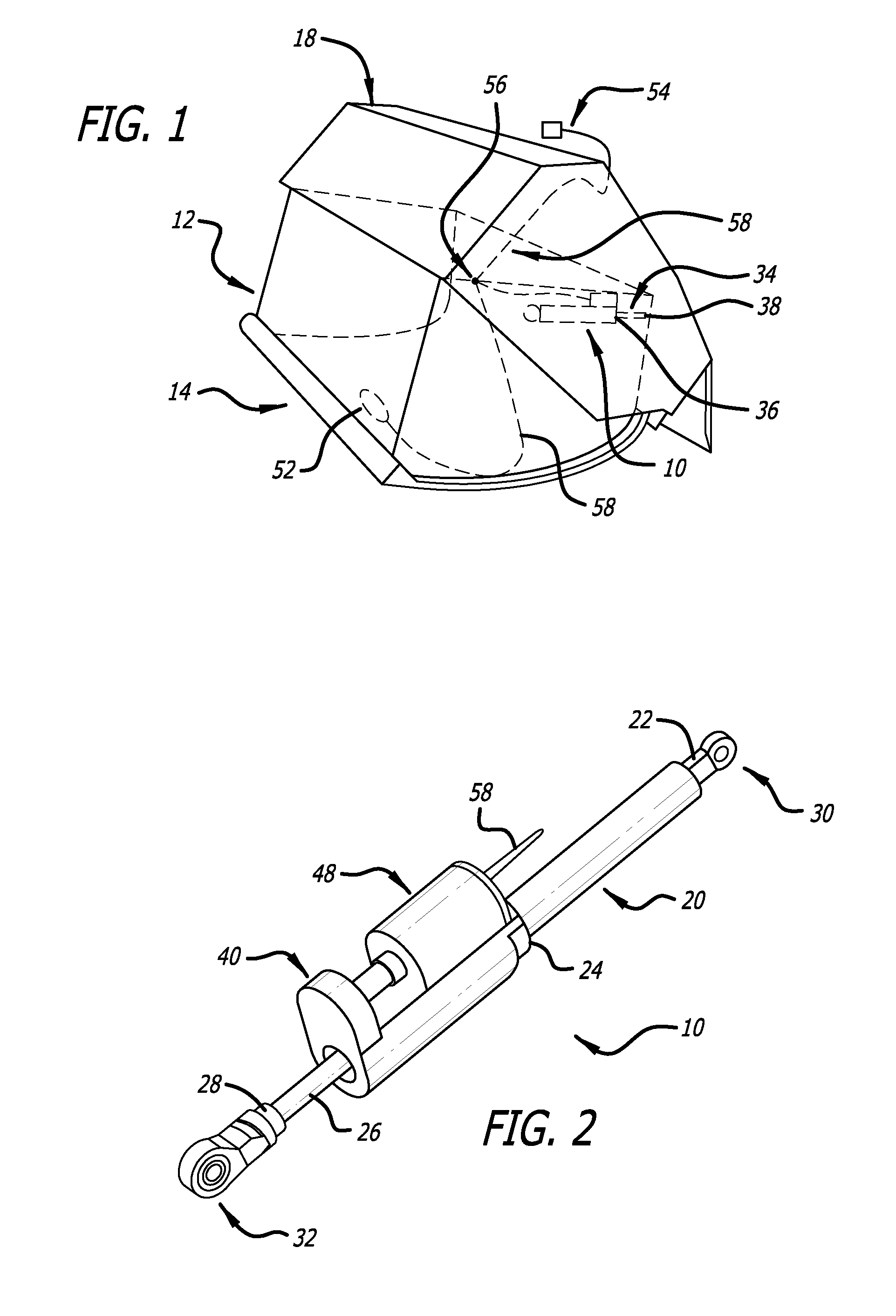
[0021]Referring to the drawings, which are provided by way of example, and not by way of limitation, the present invention provides for a lift assist mechanism 10 for providing a lift assist to a movable component 12 that can move between a lowered position 14 and a raised position 16 relative to a fixed structure 18. In a presently preferred aspect, the movable component can be a stowage bin portion cooperatively connected to the fixed structure, which can be a stationary bin support structure, so that the stowage bin portion can move between the lowered and raised positions relative to the stationary bin support structure. The assist mechanism can provide an assist to lifting the stowage bin, but will not close the bin by itself. This system as designed is an on demand or as needed type of system that is enabled when contents are loaded into the stowage bin or other movable component.

[0022]As is illustrated in FIGS. 1 and 2, the lift assist mechanism includes a lift assist spring ...


PUM


Abstract

A lift assist mechanism is provided for assisting lifting of a movable component that can move between lowered and raised positions relative to a fixed structure. The lift assist mechanism includes a lift assist spring connected to a spring shaft, and an elongated track in which an end of the lift assist spring or an end of the spring shaft are movably engaged. A spring lock restrains movement of the spring shaft when a lift assist is not required, and releases the spring shaft when a lift assist is required.

Description

CROSS-REFERENCES TO RELATED APPLICATIONS[0001]This application is based upon and claims priority from Provisional Patent Application No. 61 / 326,178, filed Apr. 20, 2010, which is incorporated by reference in its entirety herein.BACKGROUND OF THE INVENTION[0002]The present invention generally relates to lift assist mechanisms, and more particularly relates to lift assist mechanisms for stowage containers or devices, such as for overhead luggage bins for aircraft.[0003]While a powered stowage bin system is known that includes a powered stowage bin lift system, which unlatches the stowage bin and provides a powered lifting force controlled by a cabin management system, existing pivoting aircraft overhead stowage bins typically rely on force provided by an operator, such as a passenger or flight attendant, for example, to close and secure the stowage bin. Typically such pivoting aircraft overhead stowage bins have no operator assist mechanism. Springs or other simple mechanisms designed...

Claims


Application Information

Patent Timeline
IPC IPC(8): B64D11/00E05F1/10B65D55/00F16F1/06F16F9/02
CPCB64D11/003E05F1/1091Y10T16/593E05Y2900/538F16F9/56E05Y2900/502F03G1/00F16F9/0263
Inventor IVESTER, CLARENCENILSEN, ERIK E. S.BRAUER, ROBERT K.
Owner BE INTPROP
Learn More