High efficiency cogeneration system and related method of use

a cogeneration system and high efficiency technology, applied in steam use, machines/engines, emergency power supply arrangements, etc., can solve the problems of carbon monoxide build-up in the residence, waste of expensive fossil fuels, and many co-generation systems that fail to adequately harvest the heat by-product created

Inactive Publication Date: 2011-10-20
EVERLITE HYBRID INDS
View PDF20 Cites 28 Cited by
  • Summary
  • Abstract
  • Description
  • Claims
  • Application Information

AI Technical Summary

Benefits of technology

[0012]The invention is also directed at a control system that includes a control panel, a battery, an automatic transfer switch and a crediting meter that connects to the outside electricity grid. The control panel may include both a regulator and filter which helps harmonize the electricity generated by the modified combustion engine for use by both the residential or commercial facility and the outside electricity grid. The battery connects to the control panel and stores electricity generated by the cogeneration system. This battery further includes (and is connected to) an automatic transfer switch capable of drawing electricity as needed by a breaker panel. The breaker panel helps fuel and supply energy to the various appliances throughout a residential or commercial facility. Finally, the crediting meter records the amount of electricity sold back to the power authority operating the electricity grid.

Problems solved by technology

First, current cogeneration systems still create a certain degree of byproduct from the burning of fossil fuels that must be released into the atmosphere.
This creates a secondary safety issue as there is a risk that unless this toxic byproduct is sufficiently vented that it could cause a build up of carbon monoxide within the residence.
Second, most of the heat engines used in micro-cogeneration systems are not highly efficient resulting in waste of expensive fossil fuels.
Finally, many co-generation systems fail to adequately harvest all of the heat by-product created from the heat engines—which could be used to heat air and water used throughout the residence.

Method used


Image

  • High efficiency cogeneration system and related method of use
  • High efficiency cogeneration system and related method of use
  • High efficiency cogeneration system and related method of use

Examples


Embodiment Construction

[0020]The present invention will now be described more fully hereinafter with reference to the accompanying drawings, in which preferred embodiments of the invention are shown. This invention may, however, be embodied in many different forms and should not be construed as limited to the embodiments set forth herein. Rather, these embodiments are provided so that this disclosure will be thorough and complete, and will fully convey the scope of the invention to those skilled in the art. Like numbers refer to like elements throughout.

Positioning and Location of System

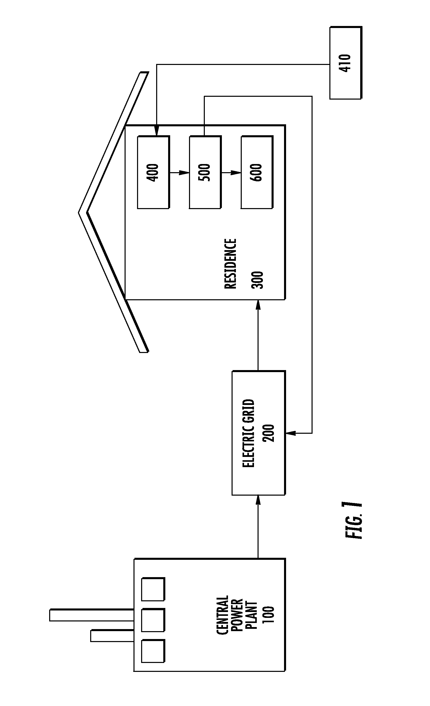
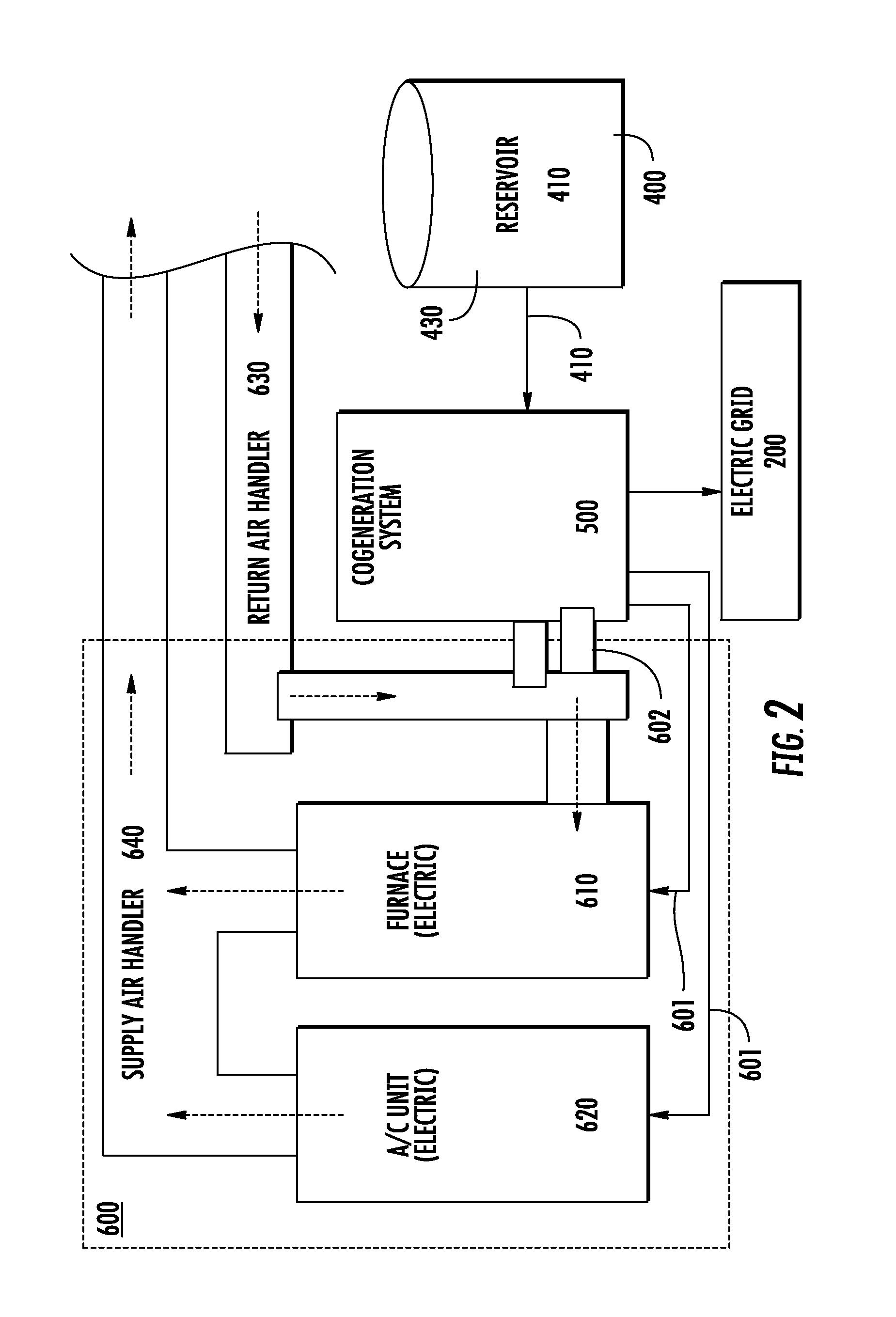
[0021]FIG. 1 and FIG. 2 both illustrate, by way of example, one positioning and location of the preferred cogeneration system 500. FIG. 1 provides a general illustration of a conventional centralized power generation system. Here, a central power plant 100 generates electricity for disbursement to a plurality of various residential and commercial facilities 300 throughout a distinct geographic area. Such central power plan...


PUM


Abstract

The invention is directed to a high efficiency cogeneration system capable of creating electricity and usable heat. The invention includes a fuel source, which can be a reservoir filled with a fossil fuel. The fuel source feeds a modified combustion engine that can turn a shaft to power an alternator to create electricity. The combustion engine creates hot gases that are treated by a catalytic converter. The byproduct and hot gases are then fed into one or more cooling manifolds.

Description

FIELD OF THE INVENTION[0001]This invention is directed toward a cogeneration system that employs a catalytic converter and one or more cooling manifolds to increase efficiency in generating electricity as well as usable heat.BACKGROUND OF THE INVENTION[0002]Cogeneration represents a relatively new concept in the field of generating electricity. Traditionally, electricity has been created at centralized facilities—typically through burning a fossil fuel like coal—which is then transported through an electricity grid to individual residential and commercial facilities.[0003]Within the past several years, cogeneration systems have been developed to essentially reduce both need and reliance on these grids. More specifically, cogeneration systems employ a heat engine (typically a combustion engine) or power station located at the residential or commercial facility itself to simultaneously generate both electricity and useful heat. Most cogeneration systems use a centralized reservoir of ...

Claims


Application Information

Patent Timeline
Patent Type & Authority Applications(United States)
IPC IPC(8): F02B63/04H02J9/08F01N3/10F24D18/00
CPCF24D2200/04F24H1/0027F28D7/106Y02E20/14F28D7/02F24H2240/02F24D18/00F24D2103/13F24D2105/00F24D2101/70Y02T10/12
Inventor KAISER, STEWARD
Owner EVERLITE HYBRID INDS
Why Eureka
Try Eureka