
Bumper crossbeam as component of a bumper of a motor vehicle

a technology of bumper and crossbeam, which is applied in the directions of bumpers, vehicle safety arrangments, transportation and packaging, etc., can solve the problems of dimensional precision of the end product, and achieve the effects of fast fabrication, easy production, and fast adaptability

Inactive Publication Date: 2011-10-20
BENTELER AUTOMOBILTECHNIK GMBH
View PDF22 Cites 11 Cited by
  • Summary
  • Abstract
  • Description
  • Claims
  • Application Information

AI Technical Summary

Benefits of technology

[0008]The present invention resolves prior art problems by combining the outer and inner sections in a manner according to the present invention so as to be able to realize different deformation resistances through variation of the configuration of the inner section. This can be achieved without altering the outer geometry of the outer section. Manufacture of a bumper crossbeam according to the invention is cost-efficient and allows a wide spectrum as far as material selection, wall thickness conditions, and selection of the inner geometry are concerned. As there is no need to execute complicated shaping works on a single component for the entire cross sectional structure, unnecessary doubling of the starting material is for example avoided so that the overall production process becomes more economical. In addition, the wall extending from a front section zone of the outer section to a rear section zone of the outer section serves a reinforcement web.
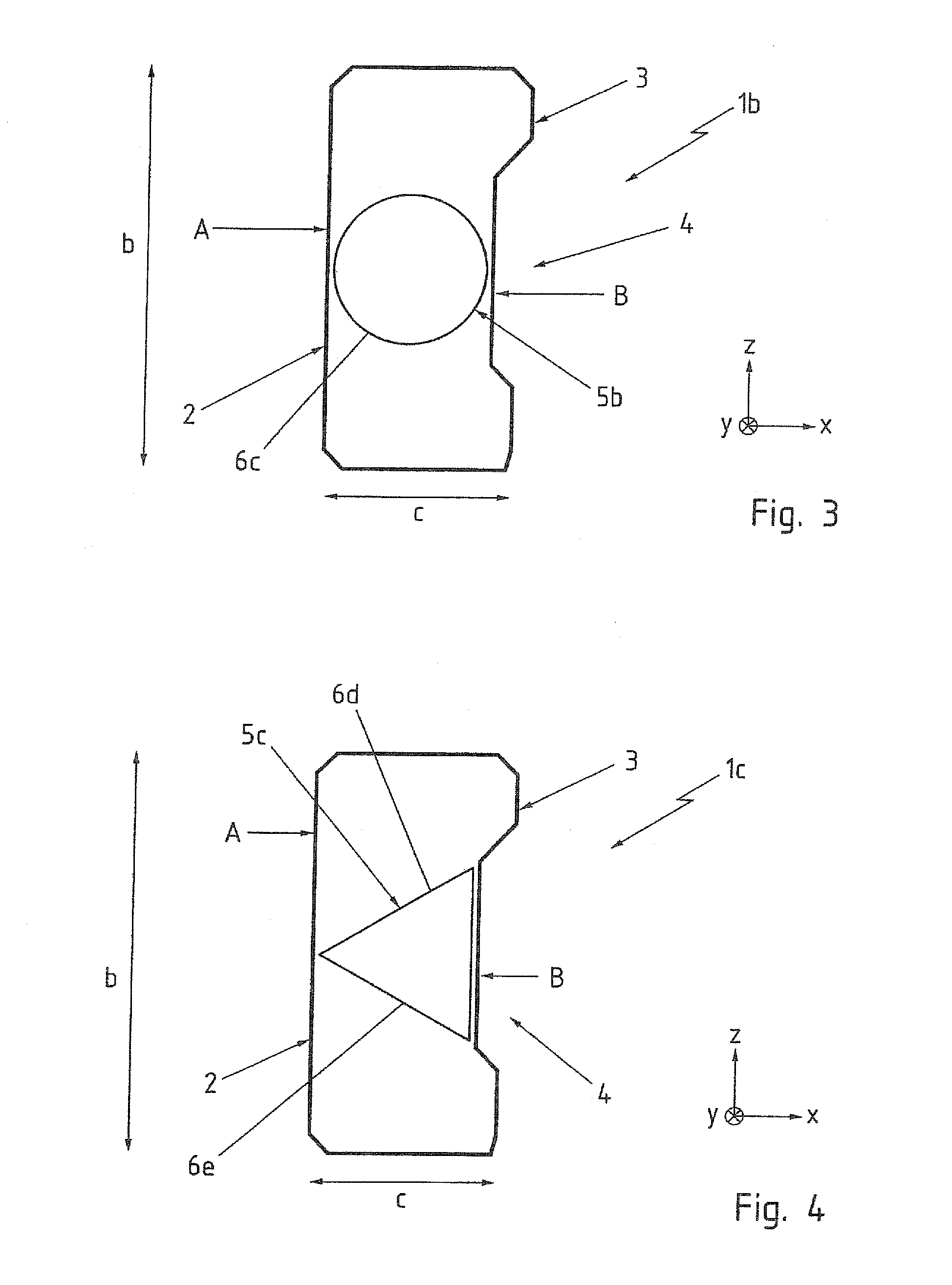
[0012]According to another advantageous feature of the present invention, the inner section may also be constructed as a closed hollow section. So long as the inner section is arranged as closed hollow section in the outer section, the inner section has advantageously a round cross section. As a result, a smaller circumference and thus a smaller weight are realized in comparison to a rectangular cross section, when, for example, the maximum outer dimensions and wall thicknesses are the same. Still, the invention affords the possibility to provide the inner section with an angled cross section for stiffening the outer section.
[0015]According to another advantageous feature of the present invention, the at least one wall of the inner section may be provided with at least one opening to reduce a deformation resistance of the inner section. This not only reduces weight but also enables to adjust the stiffness to a desired level.
[0016]According to another advantageous feature of the present invention, at least one of the sections zones of the outer section can be configured as a reinforcing embossment. As a result, the stiffness of the bumper crossbeam can be increased. Suitably, the region of the reinforcing embossment is recessed behind the neighboring regions of the outer section.
[0019]According to another advantageous feature of the present invention, the inner section has a wall thickness which can be smaller by 25% to 50% than a wall thickness of the outer section. As a result, a bumper crossbeam can be made economically and lightweight. Advantageously, the inner section of the bumper crossbeam may have has a wall thickness of 1.8 mm and the outer section a wall thickness of 2.5 mm. Combining different contours and wall thicknesses for the inner and outer sections of the bumper crossbeam affords for the first time a fast fabrication to meet most different demands. Even though, the outer section and also the inner section undergo a continuous roll-forming process, varying material thicknesses can still be implemented in a simple manner. In particular, the use of tailored blanks is possible for the inner section and / or the outer section, i.e. sheet metal blanks which are comprised of different material qualities and / or sheet metal thicknesses. In particular the use of tailored rolled blanks is possible which have regions of varying sheet metal thicknesses through rolling operation. There is no need to oversize regions of the contour. The targeted reduction in wall thickness results in a potential weight saving of up to 10% compared to conventionally manufactured crossbeams.
[0020]Moreover, protracted and occasionally complicated sequences of shaping processes are eliminated because the simple placement within one another of two sections which are easy to make renders the production fast and adaptable. In addition, a complicated pre-manufacture of the metal sheets to be contoured with required tolerances by preceding assembly of sheet metal strips of varying thickness and / or quality becomes superfluous. The rapid and simple combination possibility of different contours, material qualities, and wall thicknesses provides therefore an economical manufacturing solution which can be modified in a short time to suit changing demands.

Problems solved by technology

This requires various rolling and winding processes of the starting material and complex combination of joining and shaping working operations.
In particular, when methods are involved which include different joining processes for producing varying material thicknesses in the run-up to the shaping operation, problems have been encountered in connection with dimensional precision of the end product.

Method used


Image

  • Bumper crossbeam as component of a bumper of a motor vehicle
  • Bumper crossbeam as component of a bumper of a motor vehicle

Examples


first embodiment

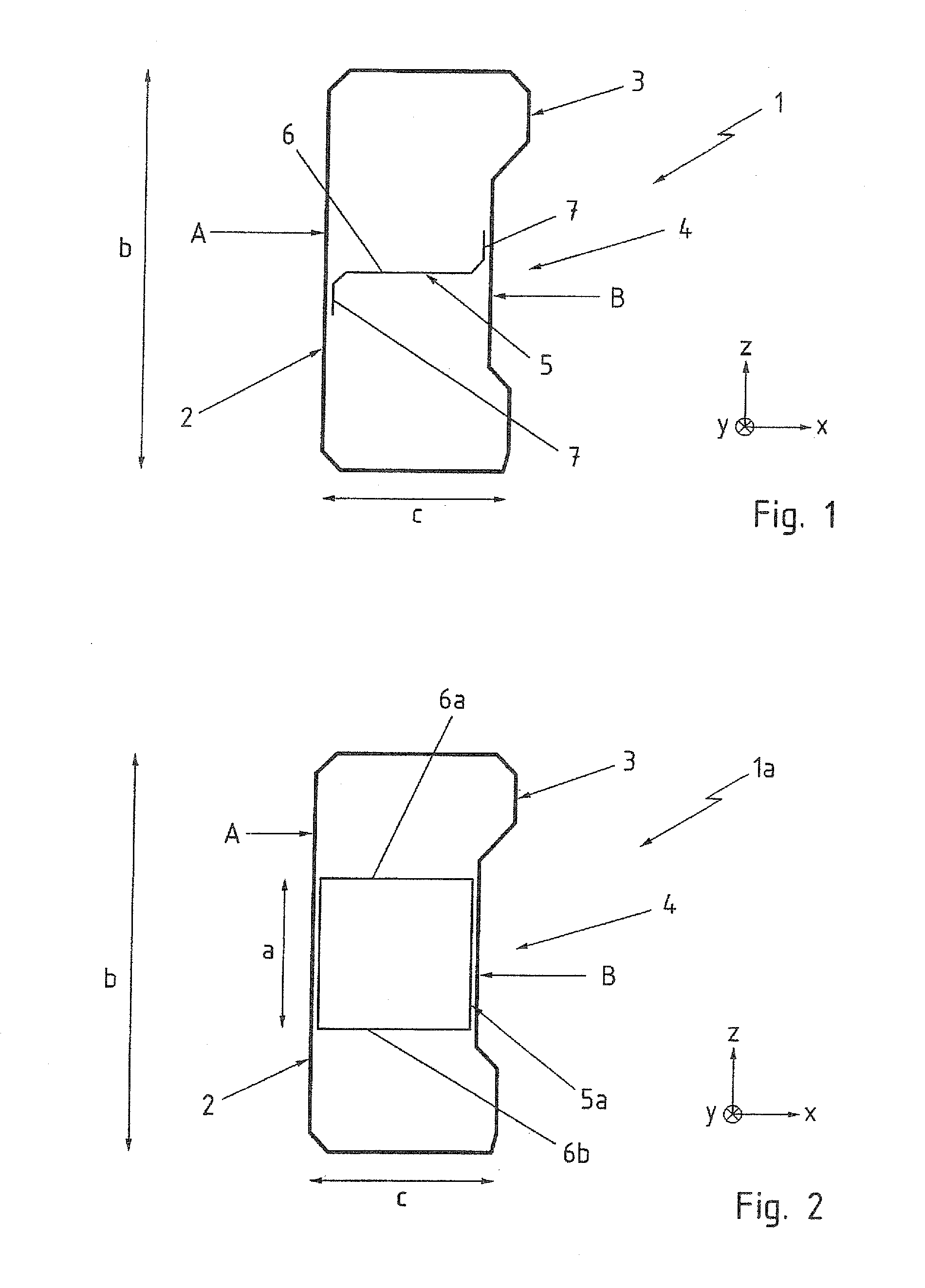
[0027]Turning now to the drawing, and in particular to FIG. 1, there is shown a schematic side view of a bumper crossbeam according to the invention, generally designated by reference numeral 1. The bumper crossbeam 1 has a substantially rectangular contour in cross section, defined by an outer section 2. The outer section 2 is formed by a hollow section 3. The outer cross sectional dimensions of the hollow section 3 indicate that a height b of the outer section 2, as measured in vertical direction z, is at least twice as high as its depth c measured perpendicular to the height b.

[0028]The component length extending in longitudinal axis of the bumper crossbeam 1 is not shown in greater detail, i.e. a yard ware produced by a continuous process is involved here.

[0029]The cross section of the outer section 2 is beveled in the corners of its contour and has a rear section zone A and a front section zone B on the opposite side. The contour in the section zone B of the outer section 2, co...

second embodiment

[0031]FIG. 2 shows a schematic side view of a bumper crossbeam according to the invention, generally designated by reference numeral 1a. In the following description, parts corresponding with those in FIG. 1 will be identified, where appropriate for the understanding of the invention, by corresponding reference numerals followed by an “a”. In this embodiment, the bumper crossbeam 1a includes the outer section 2 as hollow section, illustrated in FIG. 1. An inner section 5a is formed by a hollow section of rectangular cross section, with a wall 6a and a wall 6b respectively extending from the rear section zone A to the reinforcing embossments 4 in the section zone B. The inner section 5a has a height a measured in vertical direction z. The height a of the inner section 5a does not extend over the entire height b of the outer section 2 but is restricted only to the region of the front section zone B where the reinforcing embossment 4 is present.

third embodiment

[0032]FIG. 3 shows a schematic side view of a bumper crossbeam according to the invention, generally designated by reference numeral 1b. In the following description, parts corresponding with those in FIG. 1 will be identified, where appropriate for the understanding of the invention, by corresponding reference numerals followed by a “b”. In this embodiment, the bumper crossbeam 1b also includes the outer section 2 as hollow section, illustrated in FIG. 1. Accommodated in the outer section 2 is an inner section 5b which is realized by a round hollow section in cross section. A rotation symmetric wall 6c of the inner section 5b also extends from the rear section zone A towards the reinforcing embossment 4 in the front section zone B.


PUM


Abstract

A bumper crossbeam for a motor vehicle includes an outer section configured as a roll-formed hollow profile which is closed at least in some areas. At least one inner section, configured as a separate component, is arranged in the outer section and connected to the outer section. The inner section has at least one wall extending from a front section zone of the outer section to a rear section zone of the outer section.

Description

CROSS-REFERENCES TO RELATED APPLICATIONS[0001]This application claims the priority of German Patent Application, Serial No. 10 2009 043 022.9-21, filed Sep. 28, 2009, pursuant to 35 U.S.C. 119(a)-(d), the content of which is incorporated herein by reference in its entirety as if fully set forth herein.BACKGROUND OF THE INVENTION[0002]The present invention relates to a bumper crossbeam as component of a bumper of a motor vehicle.[0003]The following discussion of related art is provided to assist the reader in understanding the advantages of the invention, and is not to be construed as an admission that this related art is prior art to this invention.[0004]Motor vehicles have bumpers which are arranged in the front and rear zones of the vehicle. Load-Bearing component is a crossbeam which is connected on both its end zones via crash boxes with the side rails of the vehicle. Plastic casings can be provided to cover the crossbeam to the outside and are intended i.a. to match the optics ...

Claims


Application Information

Patent Timeline
IPC IPC(8): B60R19/02
CPCB60R2019/1826B60R19/18
Inventor HANDING, CHRISTIANROLL, MICHAELPOSSBERG, STEPHAN
Owner BENTELER AUTOMOBILTECHNIK GMBH
Learn More