Bi-directional inductive power transfer

Active Publication Date: 2011-10-20
AUCKLAND UNISERVICES LTD
View PDF9 Cites 171 Cited by
  • Summary
  • Abstract
  • Description
  • Claims
  • Application Information

AI Technical Summary

Benefits of technology

[0027]Preferably the controller is further adapted to control the direction of power flow by causing the pickup converter to either lag or lead the primary conductive path voltage by a required phase angle, thereby enabling bi-directional power transfer between the pickup and the primary side.

Problems solved by technology

Presently, there is no known IPT system, or more particularly no known power controller for an IPT system, which facilitates bi-directional power flow in a single system.

Method used


Image

  • Bi-directional inductive power transfer
  • Bi-directional inductive power transfer
  • Bi-directional inductive power transfer

Examples


example 2

[0089]According to an alternative embodiment of an IPT system which may otherwise be identical to that of the first example above, the secondary controller may be adapted to control the pickup output voltage by varying its inverter output magnitude (e.g. varying the converter output pulse widths using the H-bridge magnitude control scheme described above with respect to the primary inverter / rectifier, through pulse-width modulation of the converter output, or varying the output voltage using any other techniques known in the art), but maintain a fixed relative phase angle between the primary and secondary converters of + / −90°. The advantage of this embodiment is that the phase angle of 90° between the current and voltage results in unity power factor operation.

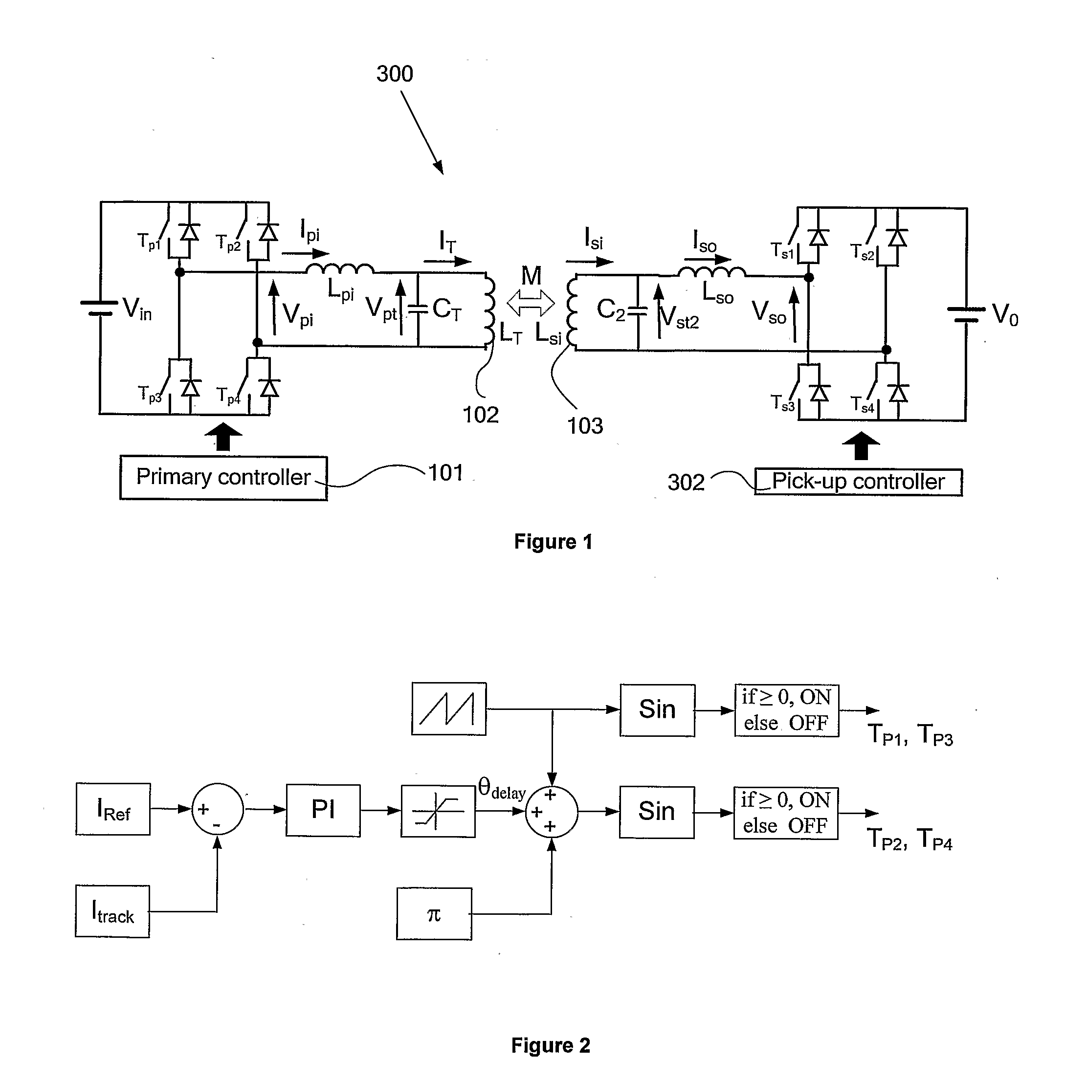
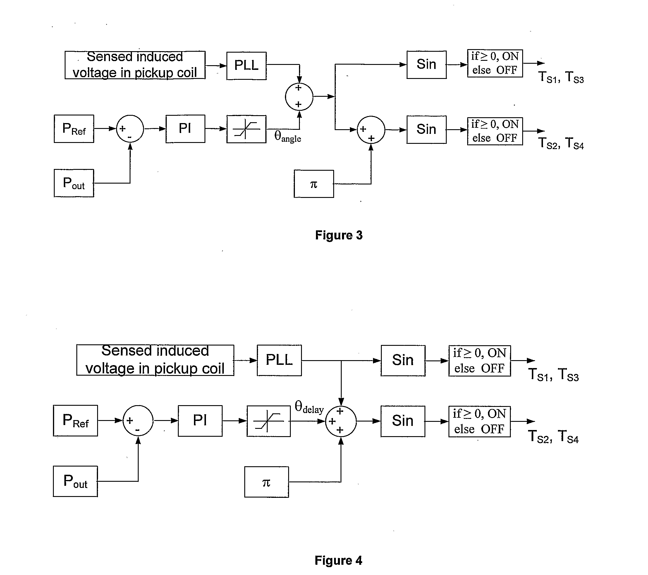
[0090]A block diagram of a secondary controller which maintains a relative phase angle of 90° is shown in FIG. 4. A proportional-integral control algorithm is used to determine an appropriate delay θdelay between the driving s...

example 3

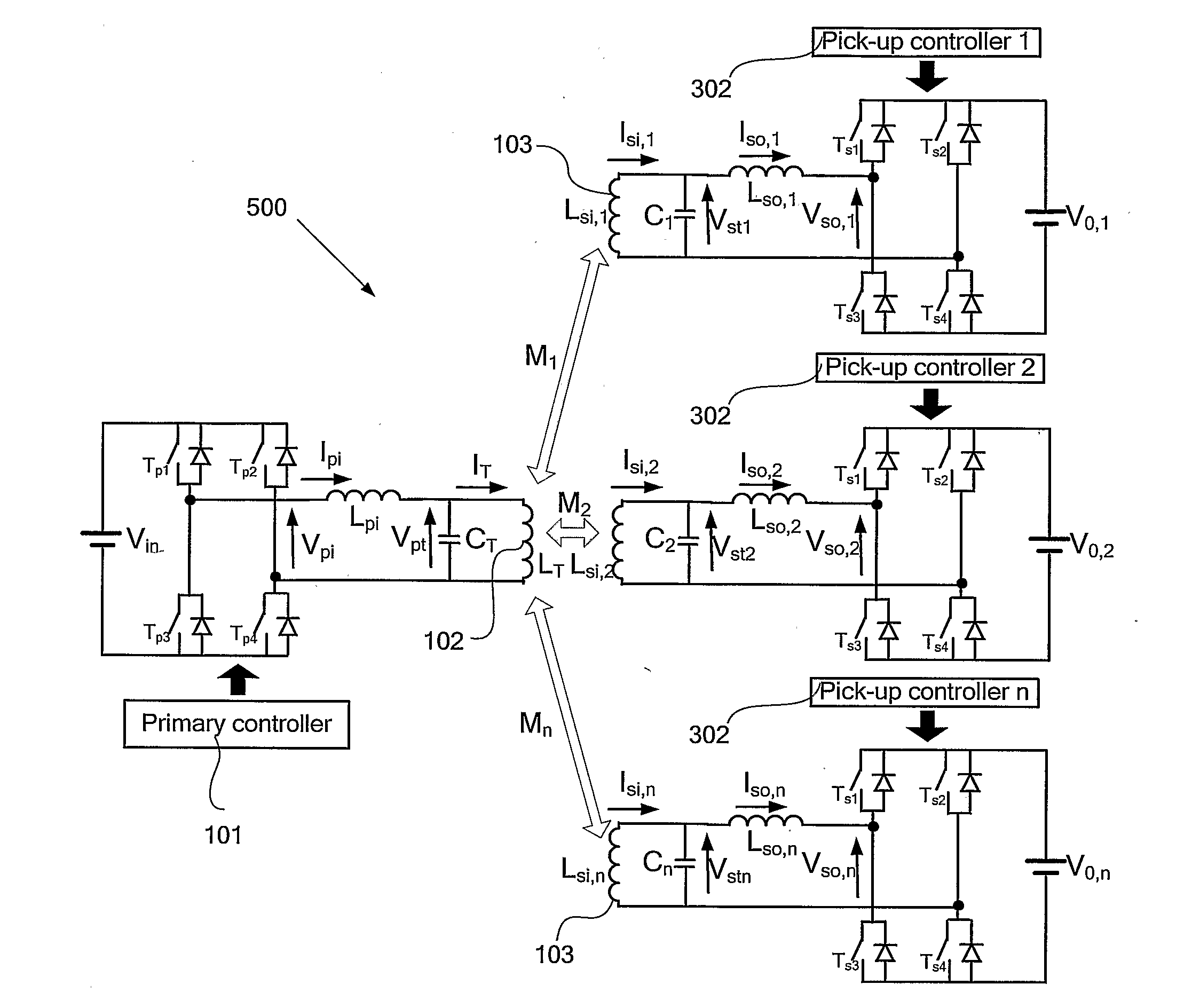
[0093]In many IPT systems, there may be multiple pickups inductively coupled with a single primary conductive path and power supply at any one time. The power controller of the present invention also has application in such systems, and a schematic of a bi-directional multiple pickup inductive power system 500 is shown by way of example in FIG. 5. The IPT system 500 comprises a similar primary side as that shown in the single pickup system example of FIG. 1, but may include two or more pickup circuits in the secondary side of the system, each pickup circuit also being similar or identical to the single pickup of FIG. 1.

[0094]In the forward mode of a multiple pickup system such as the system 500, the primary controller is preferably configured to maintain a constant current in the primary conductive path, unless all loads are removed from the system 500. The primary side controller 101 measures and maintains the track current IT by varying the voltage magnitude as necessary, either t...

example 4

[0099]In the multiple pickup system 500, one or more pickups may be supplying power to the system 500 by inductive coupling with the primary conductive path 102 while one or more other pickups may simultaneously be supplying power to a load, receiving power from the power supply and / or other pickups via the same primary conductive path. If the total power supplied to the system 500 by the pickups exceeds the power supplied to loads by one or more other pickups, then the primary power controller may be configured to supply power to the input Vin. This will be illustrated below by way of an example application of the invention in which the method / system enables contactless bi-directional charging / discharging of multiple electric or hybrid vehicles from a common DC bus using reversible rectifiers / inverters and phase modulation. Using the invention, the electric vehicles can be used both for transportation and energy storage / supply.

[0100]In this example application, the outputs of all p...


PUM

PropertyMeasurementUnit
phase angleaaaaaaaaaa
relative phase angleaaaaaaaaaa

Abstract

A method, apparatus, and system are provided which enables the control of contactless power transfer in an inductive power transfer system using a phase control technique. The method comprises adjusting the phase of a secondary-side converter output voltage with respect to that of a primary-side converter. The magnitude of power transfer is determined by the relative phase angle, and the direction of power transfer is determined by whether the secondary converter output voltage leads or lags the input converter voltage, thereby enabling bi-directional power transfer between the primary and secondary sides of the system. According to alternative embodiments, the method may also be used for uni-directional power transfer only, and/or the secondary converter may be operated to maintain a constant relative phase angle.

Description

FIELD[0001]This invention relates to an apparatus and method for controlling power in an inductive power transfer system. More specifically, the invention enables contactless bi-directional power flow between the primary and secondary sides of single- or multiple-pickup IPT systems by controlling the relative phase angles of converters on each side.BACKGROUND[0002]Inductive power transfer (IPT) or inductively coupled power transfer (ICPT) systems are well known and used for a number of industrial applications, and have particular advantages where traditional methods are unable to perform satisfactorily, for example clean rooms, people moving, materials handling, battery charging, or any application requiring a substantially contactless supply of power.[0003]A typical IPT system consists of three main components; an AC power supply, a primary conductive path, and one or more electrically isolated pickups coupled with a load and provided substantially adjacent the primary conductive p...

Claims


Application Information

Patent Timeline
Patent Type & Authority Applications(United States)
IPC IPC(8): H01F38/14
CPCH02J5/005Y02T90/121H02M3/33584Y02T10/7088Y02T10/7005Y02T90/16Y02T90/163Y02T90/14Y02T90/128Y02T90/127Y02T90/122Y04S10/126Y02E60/721B60L11/182B60L11/1842H02J7/025Y02T10/7072B60L53/12B60L55/00H02J7/00712Y02E60/00Y02T10/70H02J50/40H02J50/12Y02T90/12
Inventor MADAWALA, UDAYA KUMARA
Owner AUCKLAND UNISERVICES LTD
Why Eureka
Try Eureka