Switching power supply device

a power supply device and power supply technology, applied in the direction of power conversion systems, dc-dc conversion, electrical apparatus, etc., can solve the problems of adverse impact on the load device, increase in the loss of current detection resistor, and drastic drop in output voltage vo

Inactive Publication Date: 2011-10-20
TDK LAMBDA CORP
View PDF4 Cites 19 Cited by
  • Summary
  • Abstract
  • Description
  • Claims
  • Application Information

AI Technical Summary

Benefits of technology

[0041]Moreover, the controller is allowed to perform a soft start control, and thus, an excessive current can be prevented from flowing through the main and rectifying switching elements immediately after the main switching element has started operating.

Problems solved by technology

Besides, the phenomenon in which the output voltage Vo drastically drops due to the sink current is called a voltage dip, exerting an adverse impact on a load device.
According to such conventional art, however, the current detection resistor of electric power consumption (maximum power rating) endurable against an output voltage Vo is needed, which eventually becomes large-sized, constraining a space for other parts.
Besides, the loss of the current detection resistor increases and therefore realization of high efficiency of the switching power supply device is hindered.
This means that the response of the output voltage Vo is extremely lagged at the time of light load, causing the instability of the output voltage Vo.
Further, at the time of heavy load, too much a current flows through the body diode to give rise to such problems that the rectifying switching element is heated, or damaged by a surge voltage generated during a reverse recovery time.

Method used


Image

  • Switching power supply device
  • Switching power supply device
  • Switching power supply device

Examples


Embodiment Construction

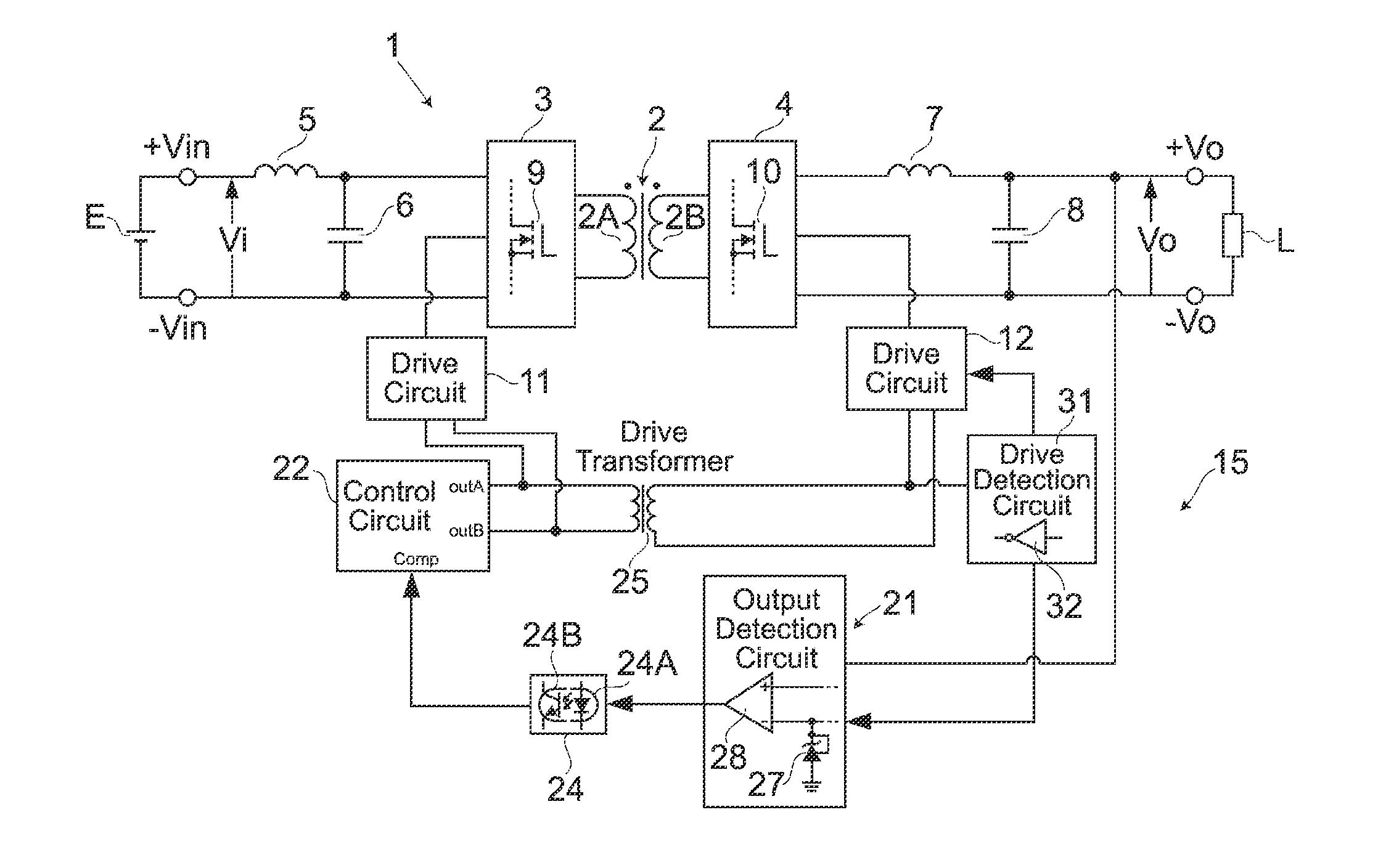
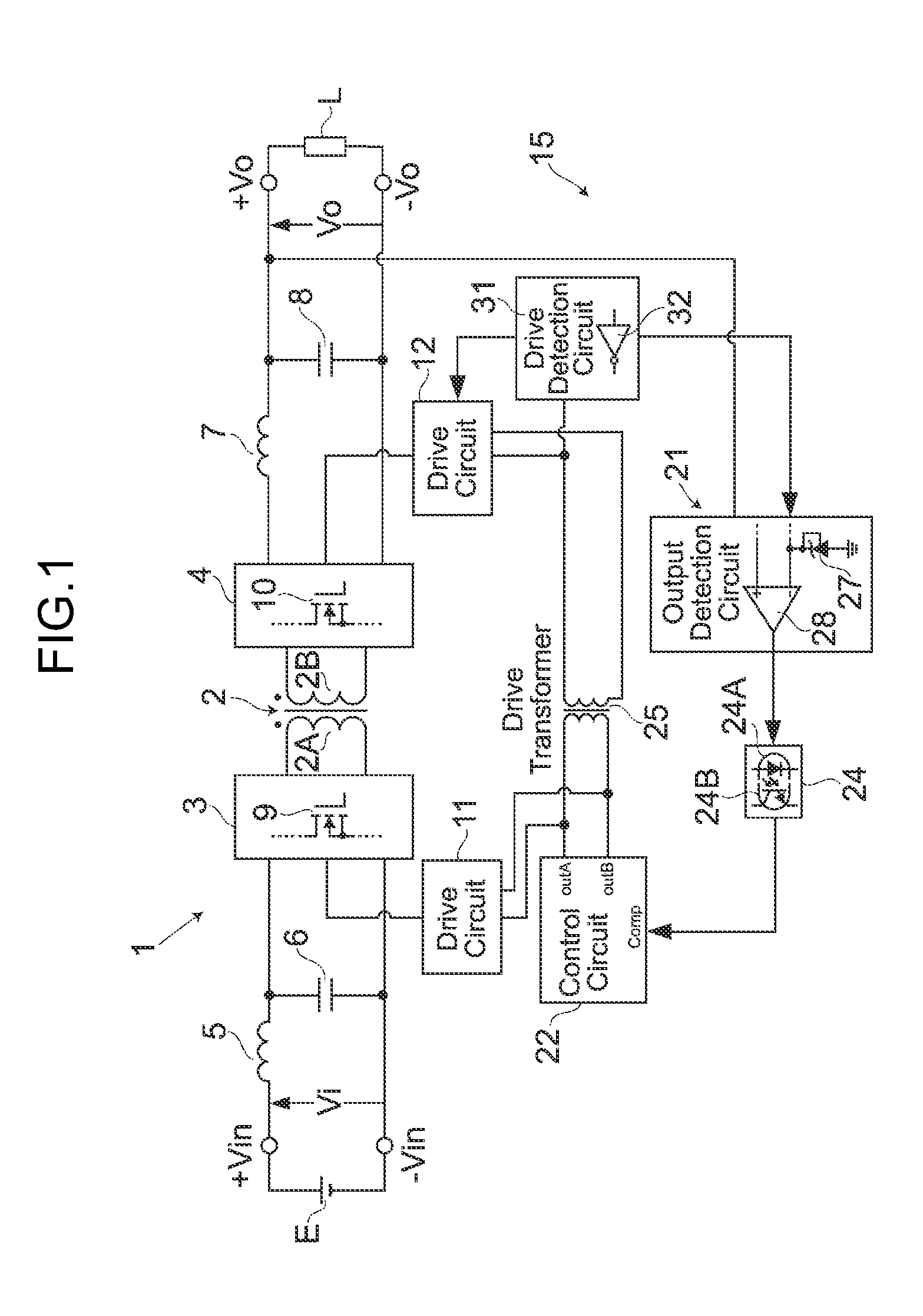
[0047]First, a description is given for an overall configuration of a switching power supply device according to the present invention based on FIG. 1. In FIG. 1, numeral symbol 1 denotes a main circuit acting as an electric power transmitter, which converts a direct-current input voltage Vi from a direct current power source E, connected across both input terminals +Vin, −Vin, into a direct-current output voltage Vo and thereafter supplies the direct-current output voltage Vo to a load L connected across output terminals +Vo, −Vo. This main circuit 1 is basically comprises a transformer 2 with primary and secondary windings 2A, 3A magnetically coupled to each other, a main switching circuit 3 provided on the primary side, that is, an input side of the transformer 2, a synchronous rectifying circuit 4 provided on the secondary side, that is, an output side of the transformer 2, a choke coil 5 and an input capacitor 6 which act as a filter circuit provided on the input side of the tr...


PUM


Abstract

A switching power supply device ensuring no voltage dip is caused by a sink current even if started with output voltage accumulated. When input voltage Vi is reapplied with output voltage Vo accumulated, supplying PWM signals to main switching element 9 and rectifying switching elements is stopped by output detection circuit 21 until a voltage produced by dividing output voltage Vo decreases to a first threshold allowable for energy caused by a sink current. Accordingly, inflow of the sink current immediately after reapplication of input voltage and the subsequent voltage dip are inhibited. Afterward, when the voltage produced by dividing the output voltage Vo decreases to the first threshold and then main switching element starts operating by PWM signal from control circuit 22, drive detection circuit 31 detects this condition to permit supplying PWM signal to rectifying switching elements 10, enabling inhibition of the subsequent inflow of the sink current.

Description

CROSS REFERENCE TO RELATED APPLICATIONS[0001]The present application claims priority under 35 U.S.C. §119 to Japanese Patent Application No. 2010-095524, filed Apr. 16, 2010, which is incorporated herein by reference.BACKGROUND OF THE INVENTION[0002]1. Field of the Invention[0003]The present invention relates to a switching power supply device provided with a synchronous rectifying circuit, particularly to a switching power supply device capable of preventing an occurrence of a voltage dip due to a sink current even if started with an output voltage accumulated or kept in a high voltage.[0004]2. Description of the Related Art[0005]In a switching power supply device, a direct-current voltage is intermittently applied to a primary winding of a transformer by an switching operation of a main switching element, and after rectifying a voltage induced in a secondary winding of the transformer, a current due to the voltage induced is smoothed through a choke coil and an output capacitor to...

Claims


Application Information

Patent Timeline
Patent Type & Authority Applications(United States)
IPC IPC(8): H02M1/36
CPCH02M3/33523H02M1/36
Inventor ONO, MASAYOSHI
Owner TDK LAMBDA CORP
Why Eureka
Try Eureka