LOW BIAS mA MODULATION FOR X-RAY TUBES

Active Publication Date: 2011-10-20
GENERAL ELECTRIC CO
View PDF4 Cites 18 Cited by
  • Summary
  • Abstract
  • Description
  • Claims
  • Application Information

AI Technical Summary

Benefits of technology

[0005]The present technique is generally directed to X-ray tubes having thermionic emitters. More specifically, according to present embodiment

Problems solved by technology

Additionally, an electrical current flowing through a thermionic emitter within

Method used


Image

  • LOW BIAS mA MODULATION FOR X-RAY TUBES
  • LOW BIAS mA MODULATION FOR X-RAY TUBES
  • LOW BIAS mA MODULATION FOR X-RAY TUBES

Examples


Example

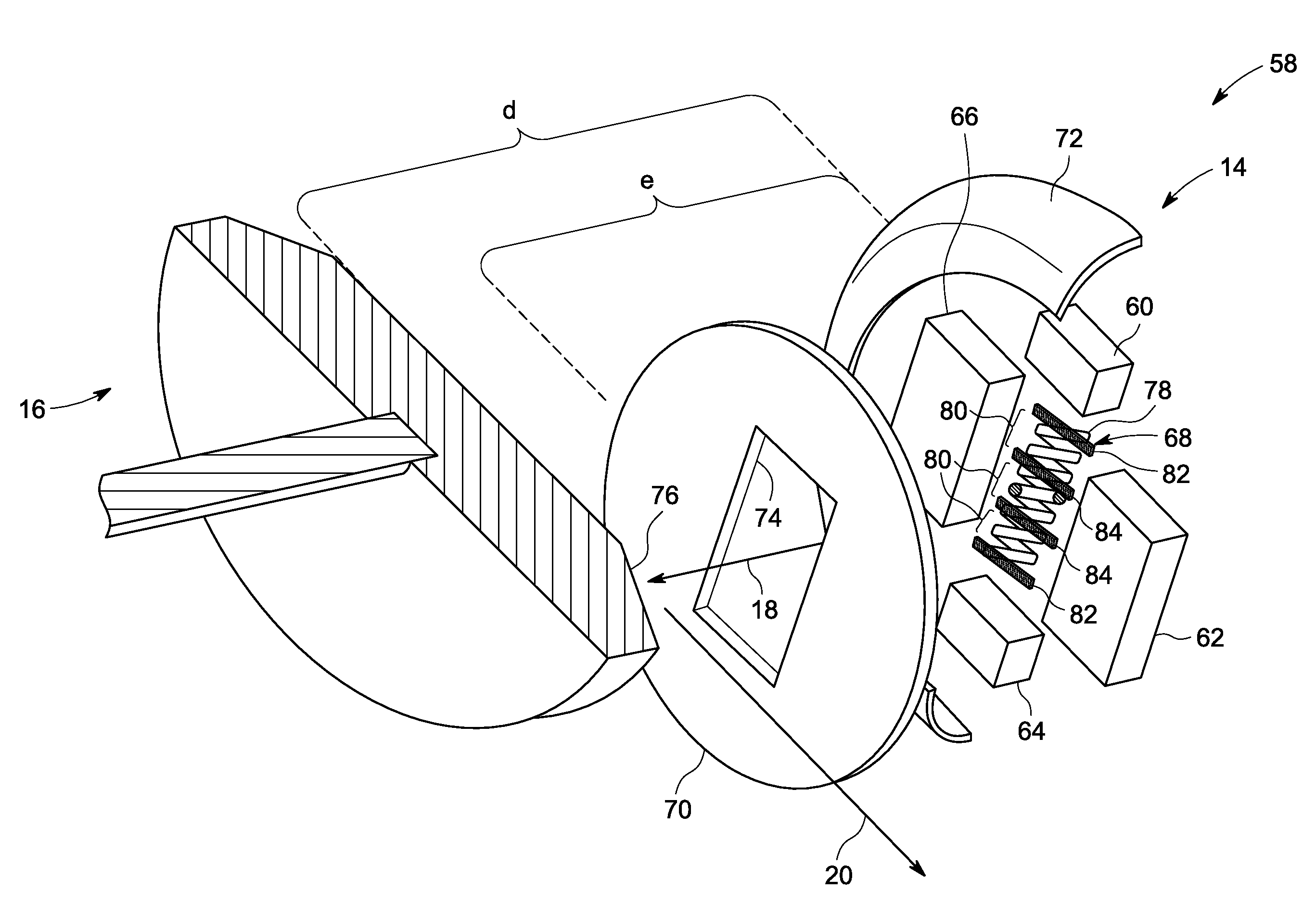
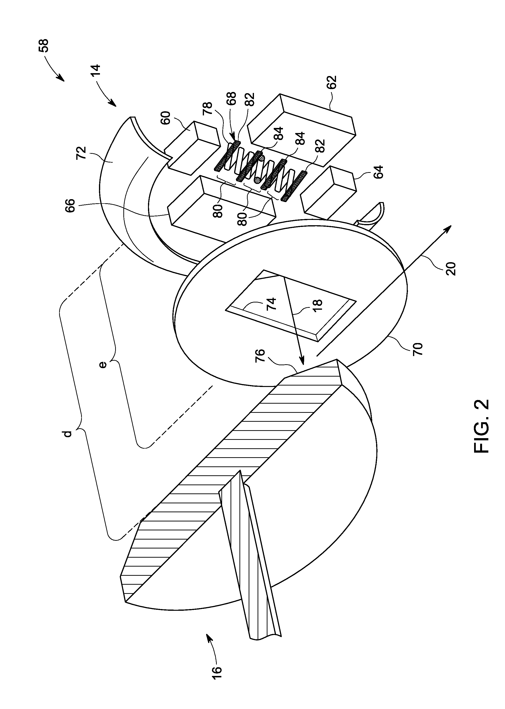
[0017]The present approaches are directed to segmented thermionic emitters within X-ray tube cathodes. The thermionic emitters may be segmented to allow milli-amp (mA) modulation of electron emission during operation. That is, X-ray tubes employing the present approaches may be operated and / or modulated (switched) on a timeframe previously inaccessible at the voltages suitable for (mA) modulation. For example, in some imaging sequences, biasing the voltage between the anode and cathode of the X-ray tube and varying the current flowing through the thermionic emitter may modulate the emission of electrons from the surface of the thermionic emitter. The extent of electrons emitted by the thermionic emitter may correspond to the amount of X-ray radiation emitted by the X-ray tube.

[0018]According to the present approaches, the amount of X-ray radiation emitted by the X-ray tube may be modulated at the thermionic emitter using relatively low current and / or low voltages. For example, in co...


PUM


Abstract

A segmented thermionic emitter is provided. The segmented thermionic emitter has, among other features, a plurality of segments substantially spanning an entire length of the thermionic emitter and aligned substantially parallel with one another. In one embodiment, the segmented thermionic emitter may allow milli-amp modulation of an X-ray tube at voltages less than approximately 2 kV.

Description

BACKGROUND OF THE INVENTION[0001]The present technique relates generally to X-ray sources. In particular, the present disclosure relates to X-ray tube cathodes, such as those contained in X-ray tubes used in medical X-ray imaging.[0002]In non-invasive imaging systems, X-ray tubes are used in both X-ray systems and computer tomography (CT) systems as a source of X-ray radiation. The radiation is emitted in response to control signals during inspection, examination or imaging sequences. Typically, the X-ray tube includes a cathode and an anode. An emitter within the cathode may emit a stream of electrons in response to heat resulting from an applied electrical current via the thermionic effect. The anode may include a target that is impacted by the stream of electrons. The target may, as a result, produce X-ray radiation and heat.[0003]The radiation spans a subject of interest, such as a human patient, and a portion of the radiation impacts a detector or a photographic plate where the...

Claims


Application Information

Patent Timeline
IPC IPC(8): H05G1/52H01J35/08H01J35/06
CPCH01J35/06H05G1/34H01J2235/068H01J35/064
Inventor LEMAITRE, SERGIO
Owner GENERAL ELECTRIC CO
Why Eureka
Try Eureka