Method of forming semiconductor patterns
a semiconductor pattern and pattern technology, applied in semiconductor/solid-state device manufacturing, basic electric elements, electric devices, etc., can solve the problems of difficult control of the uniform amount of shrinking of such a photo resist shrink step or trimming step, higher and collapsing of photo resist lines, so as to reduce the amount of pr footing and reduce the chance of patterning failure. , the effect of increasing the trimming ra
- Summary
- Abstract
- Description
- Claims
- Application Information
AI Technical Summary
Benefits of technology
Problems solved by technology
Method used
Image
Examples
experimental example 1
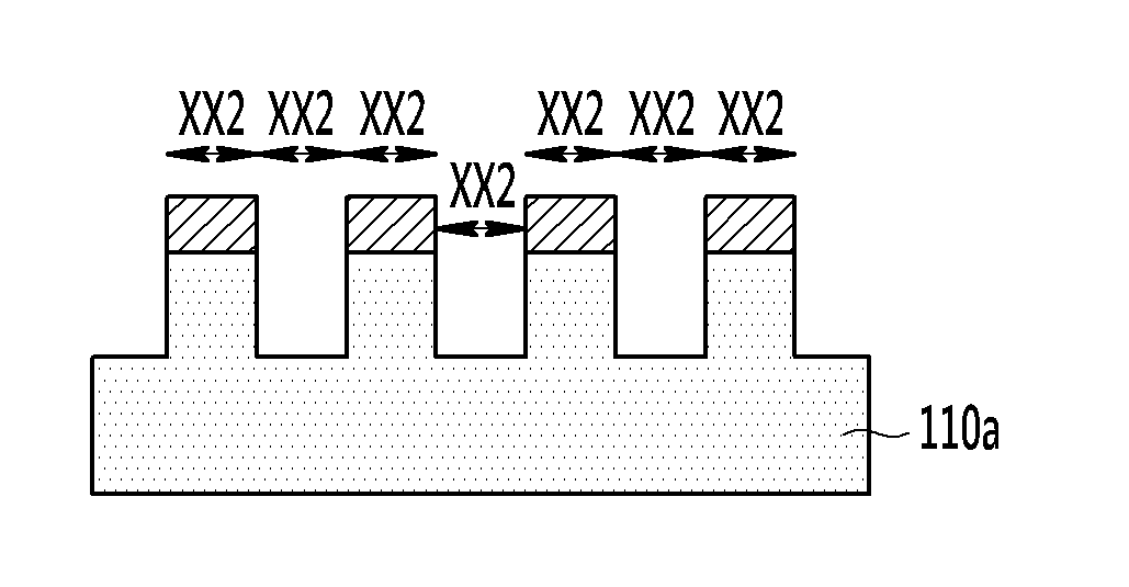
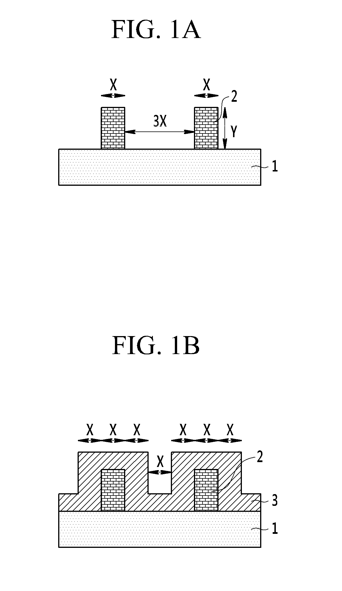
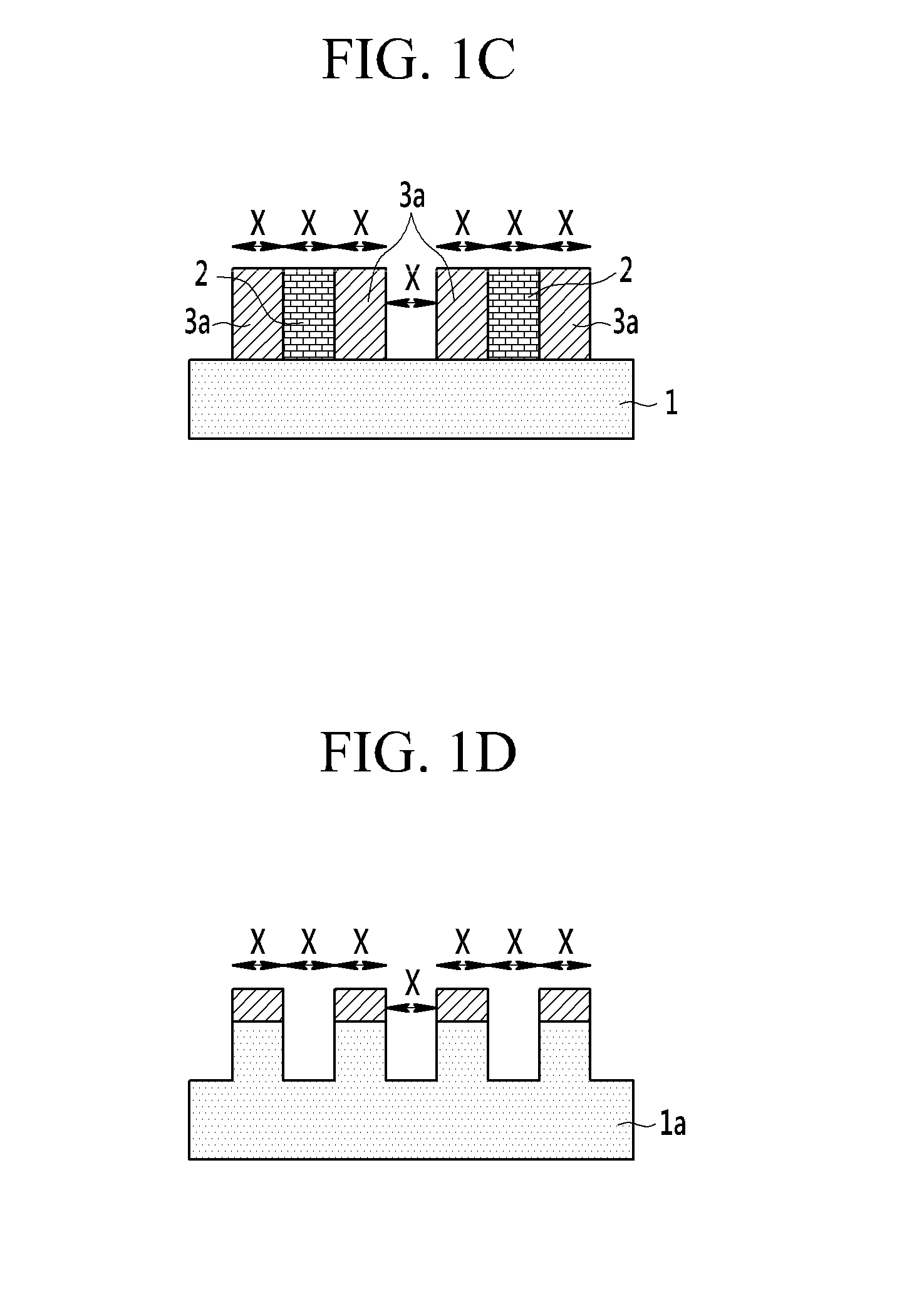
[0037]A SiO2 film deposition by PEALD on photo resist template patterns is carried out with the following conditions.
[0038]Metalorganic precursors or halosilane precursors containing Si can be used as Si precursors. In the present invention, for example, SiH2[N(C2H5)2]2 was used as a Si precursor. Susceptor temperature for heating substrate varied from room temperature to 200 degree C., preferably the susceptor temperature was 50 degree C. During deposition, process pressure is maintained in a range from 1 to 10 Torr, preferably at a value of about 3 Torr. RF plasma power is in a range from 10 to 1000 W, preferably at a value of about 200 W.
[0039]Gas flow condition is as follows.[0040]Source Ar flow rate for carrying bubbled precursor into reactor: 200 sccm[0041]Temperature of precursor container: 60° C.[0042]O2 reactant flow rate: 50 sccm[0043]Reactant Ar flow rate for flowing into reactor with oxygen: 200 sccm[0044]Main Ar flow rate for chamber / gas line purge: 200 sccm
[0045]Proces...
experimental example 2
[0051]A SiO2 film deposition by PEALD on photo resist template patterns is carried out with the following conditions.
[0052]Metalorganic precursors or halosilane precursors containing Si can be used as Si precursors. In this invention, SiH2[N(C2H5)2]2 was used as a Si precursor. Susceptor temperature for heating substrate varied from room temperature to 200 degree C., preferably the susceptor temperature was 50 degree C. During deposition, process pressure is maintained in a range from 1 to 10 Torr, preferably at a value of about 3 Torr. RF plasma power is in a range from 10 to 1000 W, preferably at a value of about 100 W to 150 W.
[0053]Gas flow condition:[0054]Source Ar flow rate for carrying bubbled precursor into reactor: 500 sccm[0055]Temperature of precursor container: 60° C.[0056]O2 reactant flow rate: 1000 sccm[0057]Reactant Ar flow rate for flowing into reactor with oxygen: 500 sccm[0058]Main Ar flow rate for chamber / gas line purge: 200 sccm[0059]Reaction space gap between sh...
PUM
 Abstract
Description
Claims
Application Information
 - R&D
- Intellectual Property
- Life Sciences
- Materials
- Tech Scout
- Unparalleled Data Quality
- Higher Quality Content
- 60% Fewer Hallucinations
Browse by: Latest US Patents, China's latest patents, Technical Efficacy Thesaurus, Application Domain, Technology Topic, Popular Technical Reports.
© 2025 PatSnap. All rights reserved.Legal|Privacy policy|Modern Slavery Act Transparency Statement|Sitemap|About US| Contact US: help@patsnap.com


