Coriolis mass flowmeter

a mass flowmeter and coriolis technology, applied in the direction of mass flow measurement devices, measurement devices, instruments, etc., can solve the problems of 0.04%, achieve the effect of preventing the wall resistance of the housing, high magnetic permeability, and compact configuration

Active Publication Date: 2011-10-27
KROHNE MESSTECHNICK GMBH & CO KG
View PDF14 Cites 9 Cited by
  • Summary
  • Abstract
  • Description
  • Claims
  • Application Information

AI Technical Summary

Benefits of technology

[0012]According to a particularly preferred design of the invention, it is provided that the thermal bridge is at least partially implemented by at thermally conductive potting of the transducer, wherein “at least partially” means that the thermal bridge can also include other components, which take part in thermal conductivity. The advantage of a thermally conductive potting is that the often differing, large electric components of the transducer directly give off their heat to the potting, without the danger that the released heat is emitted or given off by convection or radiation in the entire inner space of the housing; the thermal potting “binds” the released heat, so to speak, spatially, and further, guides it in a controlled manner by means of its geometric shape.
[0013]According to a further advantageous design of the invention, it is provided that the thermal bridge is at least partially implemented by a rigid reinforcement element, or acts as a rigid reinforcement element, wherein this reinforcement element is implemented preferably in surface contact with the housing. The reinforcement element can, for example, be realized by two stainless steel plates that are rigidly connected with the shield, pushed into the housing and mounted with the housing under mechanical stress and affixed to the housing; the attachment preferably occurs by means of spot welding (point welding). The use of such a construction ensures that a mechanically safe link is produced between the transducer and the housing, namely the resilience of the walls of the housing is prevented. It has been shown to be of particular advantage when the above measures of the implementation of a thermally conductive potting and the implementation of a non-flexible link between the transducer and the housing, which is arranged, for example, as a stainless steel plate between the thermal potting around the transducer and a wall of the housing, are provided, since a combination of the described advantages is possible in a simple manner.
[0014]According to a further teaching—implemented independently from the above-described measures, the above-described object is also met unexpectedly by an electric and/or magnetic shield being arranged around the transducer, at least in the space between the transducer and the sensor arrangement; this formulation is based on exactly the same understanding of the “to be arranged in the space” as has already been described above. It has been shown to be of particular advantage when the electric and/or magnetic shield also extends into in the space between the transducer and the housing, since a safe and comprehensive shield can be guaranteed in this manner. In particular, in connection with the above-mentioned shield, it is provided by a preferred design of the invention that the electric and/or magnetic shield is made of a thermally, highly conductive material, in particular of a magnetically soft substance with a high magnetic permeability. For this reason, the electric and/or magnetic shield, at the same time, also becomes a thermal bridge between the transducer and

Problems solved by technology

In these types of Coriolis mass flowmeters, in which the sensor arrangement and the transducer are adjacent to one another in a common volume defined by the housing, as opposed to the above-mentioned construction, the sensor arrangement and the transducer strongly interact due to their relative closeness to one an

Method used


Image

  • Coriolis mass flowmeter
  • Coriolis mass flowmeter
  • Coriolis mass flowmeter

Examples


Embodiment Construction

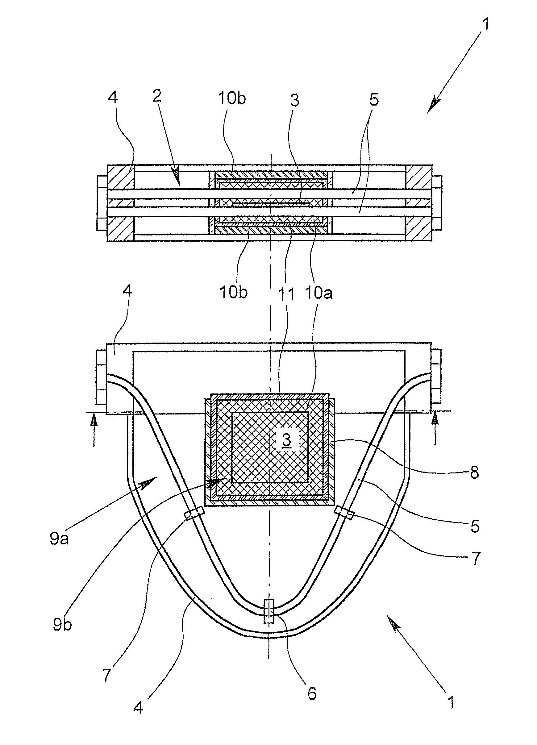
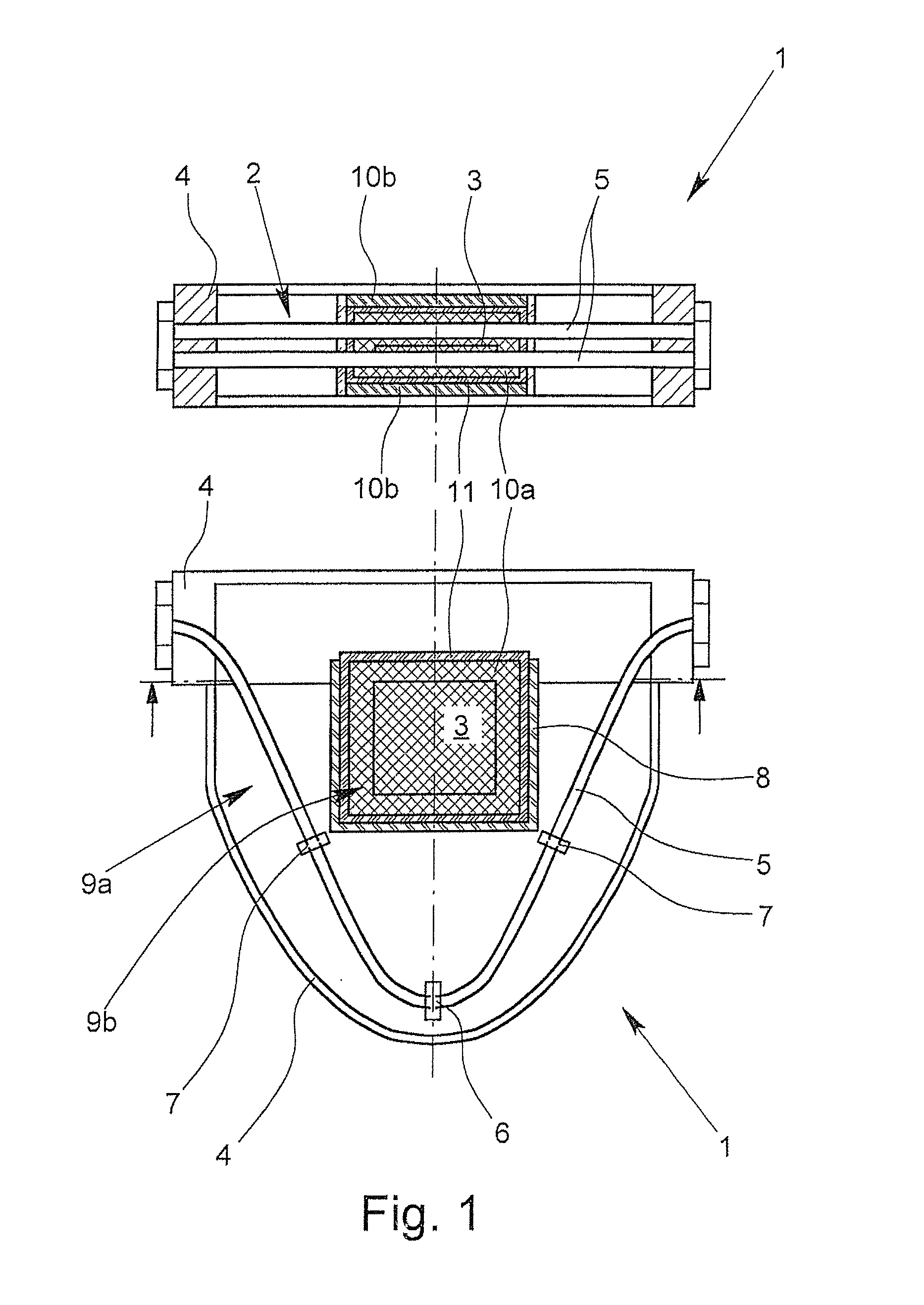
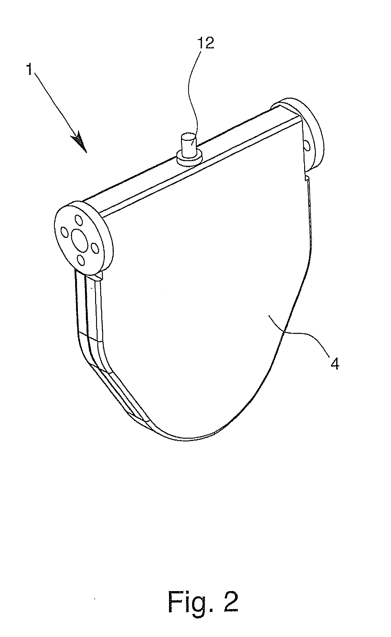
[0022]A Coriolis mass flowmeter 1 is represented in each of FIGS. 1 & 2. FIG. 1 shows the Coriolis mass flowmeter schematically from above (top) and from a side (below), as a section or a partial section. The illustrated Coriolis mass flowmeter 1 includes three main components, namely the sensor arrangement 2, a transducer 3 and a housing 4. The sensor arrangement 2 includes two measuring tubes 5 that can be excited to oscillation, an oscillation generator 6 and two oscillation sensors 7. The transducer 3 includes the evaluation and power electronics for controlling and measurement evaluation of the sensor arrangement, wherein the evaluation and power electronics are not shown in detail here beyond the extent of the printed circuit board on which transducer 3.

[0023]The measuring tubes 5 of the illustrated Coriolis mass flowmeter 1 are designed in a V-shape, wherein the transducer 3 is arranged between the legs of the V-shape of the measuring tube 5, which is why the sensor arrangeme...


PUM


Abstract

A Coriolis mass flowmeter (1) having at least one sensor arrangement (2), at least one transducer (3) and at least one housing (4), wherein the sensor arrangement (2) has at least one measuring tube (5) that can be excited to oscillation, at least one oscillation generator (6) and at least one oscillation sensor (7), wherein the transducer (3) at least in part has evaluation and power electronics for controlling and measurement evaluation of the sensor arrangement, wherein the sensor arrangement (2) and the transducer (3) are arranged adjacent to one another in a common volume defined by the housing (4). A Coriolis mass flowmeter of the described type, in which the physical interaction between the sensor arrangement and transducer is reduced, is realized by the provision of a thermal barrier (8) arranged at least in a space between the sensor arrangement (2) and the transducer (3).

Description

BACKGROUND OF THE INVENTION[0001]1. Field of the Invention[0002]The invention relates to a Coriolis mass flowmeter having at least one sensor arrangement, at least one transducer and at least one housing, wherein the sensor arrangement has at least one measuring tube that can be excited to oscillation, at least one oscillation generator and at least one oscillation sensor, wherein the transducer at least in part has the evaluation and power electronics for controlling and measurement evaluation of the sensor arrangement, wherein the sensor arrangement and the transducer are arranged adjacent to one another in a common volume defined by the housing.[0003]2. Description of Related Art[0004]Coriolis mass flowmeters of the type mentioned above are known, for example, from German Patent Application DE 10 2008 007 742 A1. In Coriolis mass flowmeters in general, a measuring tube with a flowing medium is excited into oscillation by an oscillation generator, preferably in a certain eigenform...

Claims


Application Information

Patent Timeline
IPC IPC(8): G01F1/84
CPCG01F1/8409G01F1/8477G01F1/8413G01F15/006G01F15/14
Inventor KOLAHI, KOUROSHPOREMBA, ANDREAS
Owner KROHNE MESSTECHNICK GMBH & CO KG
Why Eureka
Try Eureka