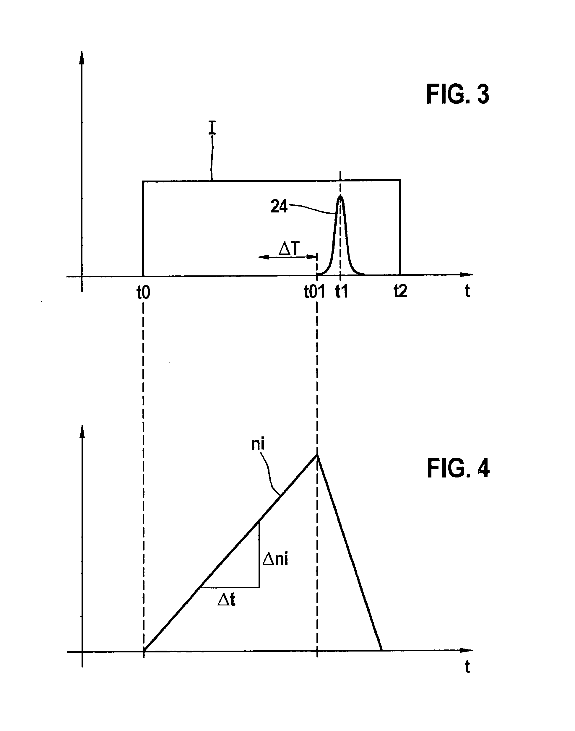
[0006]This object is attained, according to the present invention, in the case of the operating method of the type mentioned at the outset, by acting on the laser device using pumping light in such a way that a specifiable curve over time of the inversion density comes about in the laser-active solid. According to the present invention, it has been recognized that not only an absolute value of the inversion density, brought about in the laser-active solid by the action of the pumping light, has an influence on the generation of a passively Q-switched laser pulse, but particularly also the curve over time of the inversion density. Accordingly, it becomes advantageously possible, because of the method of the present invention, to achieve a desired inversion density in the laser-active solid, and with that, a desired operating behavior of the laser device, by way of a specifiable pumping light action of the laser device. In particular, because of this, the precision compared to usual methods is able to be increased with respect to the point in time at which the Q-switched laser pulse is emitted.
[0008]The selection, according to the present invention, of the
power density of the pumping light may take place, for example, by way of a control method in which the
power density of successive pumping processes is first varied until the desired pumping duration is reached that is of the
order of magnitude of twice the
fluorescence life or less. Besides the
fluorescence life of the laser-active materials used, there exist further factors such as the optical configuration of the laser device, the type of the
coupling of the pumping light into the laser device or the laser-active solid and the like, so that the optimal pumping duration or a
power density required for this is able to be ascertained for a given configuration, for instance, within the scope of an application process. According to the present invention, a variance in time of the pumping duration between the pumping
start time and the actual generation of the passively Q-switched laser pulse is particularly small when the pumping duration is less than, or equal to approximately twice the
fluorescence life of the material of the laser-active solid. An even smaller variance of the pumping duration, and consequently a further increased precision, comes about, according to the present invention, if the power density of the pumping light is selected so that the pumping duration up to the generation of the laser pulse lies within the range of the simple fluorescence life of the laser-active material. This means that, according to the present invention, the power density of the pumping light is to be selected to be sufficiently great to achieve a pumping duration in the range of the single to double fluorescence life, and thus a low variance in the pumping duration.
[0010]In one further very advantageous example embodiment of the method according to the present invention, it is provided that one should apply to the laser device, at least at times, a pumping light of a nonconstant power density and one should select the power density of the pumping light in such a way that, at least at times, a specifiable change over time comes about of the inversion density in the laser-active solid. This brings about an additional degree of freedom which, for example, directly after the pumping
start time, first makes possible an
optical pumping having a relatively low power density of the pumping light, and therefore a more protective operation of the pumping
light source. In order, nevertheless, to obtain an increased precision with respect to the occurrence in time of the passively Q-switched laser pulse, it is advantageously provided, according to the present invention, at least at times, and particularly directly before the generation of the passively Q-switched laser pulses, that one maintain a specifiable change over time of the inversion density in the laser-active solid.
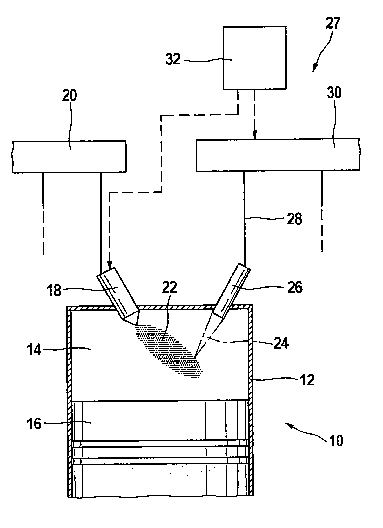
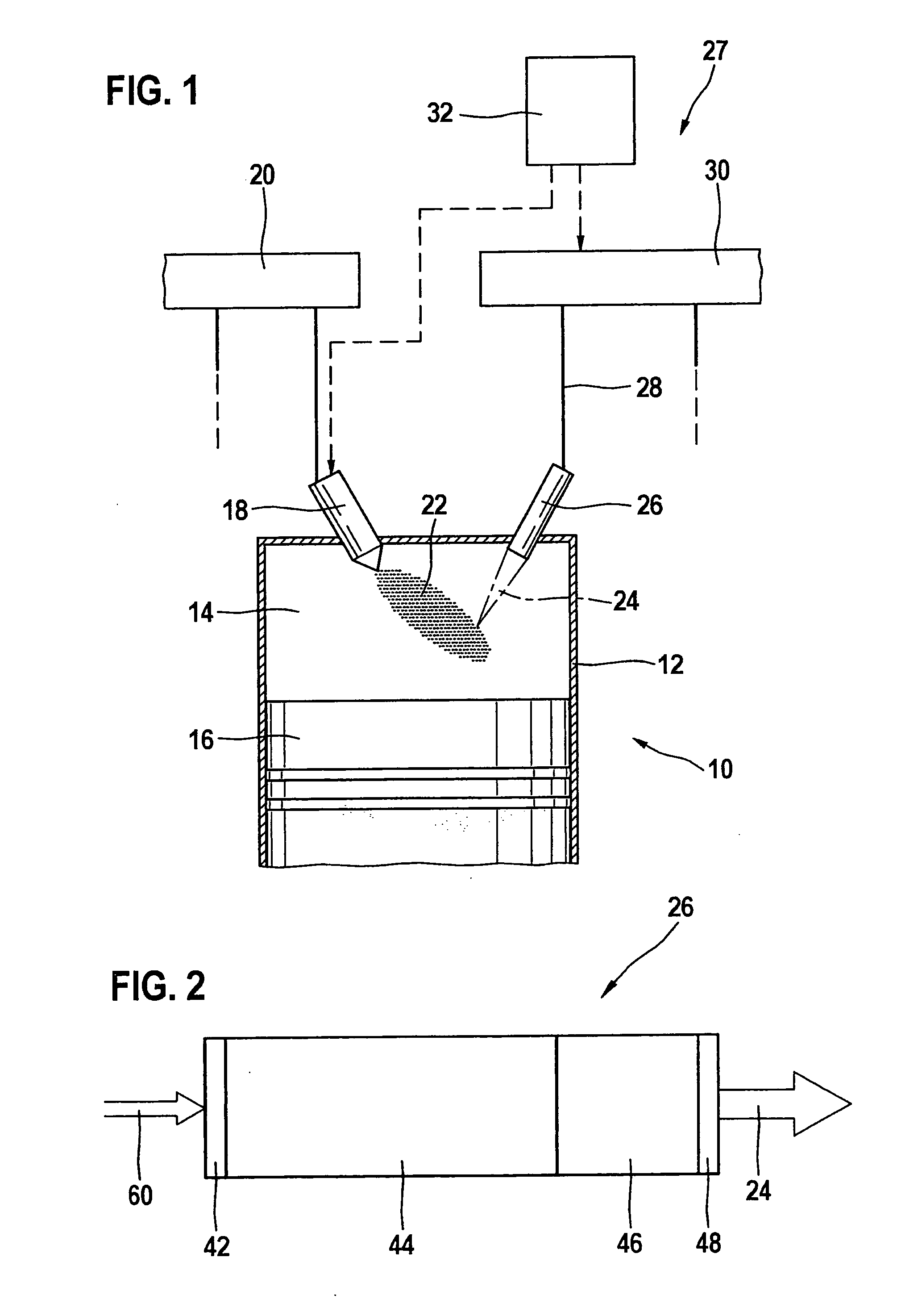
[0014]When using a pumping
light source having one or more
semiconductor laser diodes, the desired power density of the pumping light is able to be set particularly easily by specifying a corresponding current through the
semiconductor laser diodes.

