Solar light collecting method in multi-tower beam-down light collecting system

Inactive Publication Date: 2011-10-27
COSMO OIL CO LTD +1
View PDF6 Cites 14 Cited by
  • Summary
  • Abstract
  • Description
  • Claims
  • Application Information

AI Technical Summary

Benefits of technology

[0022]According to the present invention, in the multi-tower beam-down light collecting system, each of the heliostats that are dispersedly arranged on the g

Problems solved by technology

Therefore, an issue in installing the heliostats is that, in order to obtain large quantity of energy, it is necessary to increase the mirror surface area of the heliostats or to increase the number of

Method used


Image

  • Solar light collecting method in multi-tower beam-down light collecting system
  • Solar light collecting method in multi-tower beam-down light collecting system
  • Solar light collecting method in multi-tower beam-down light collecting system

Examples


Example

Embodiment 1

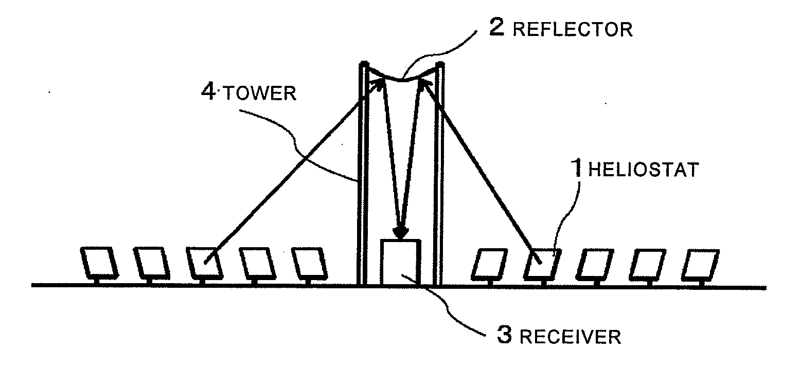
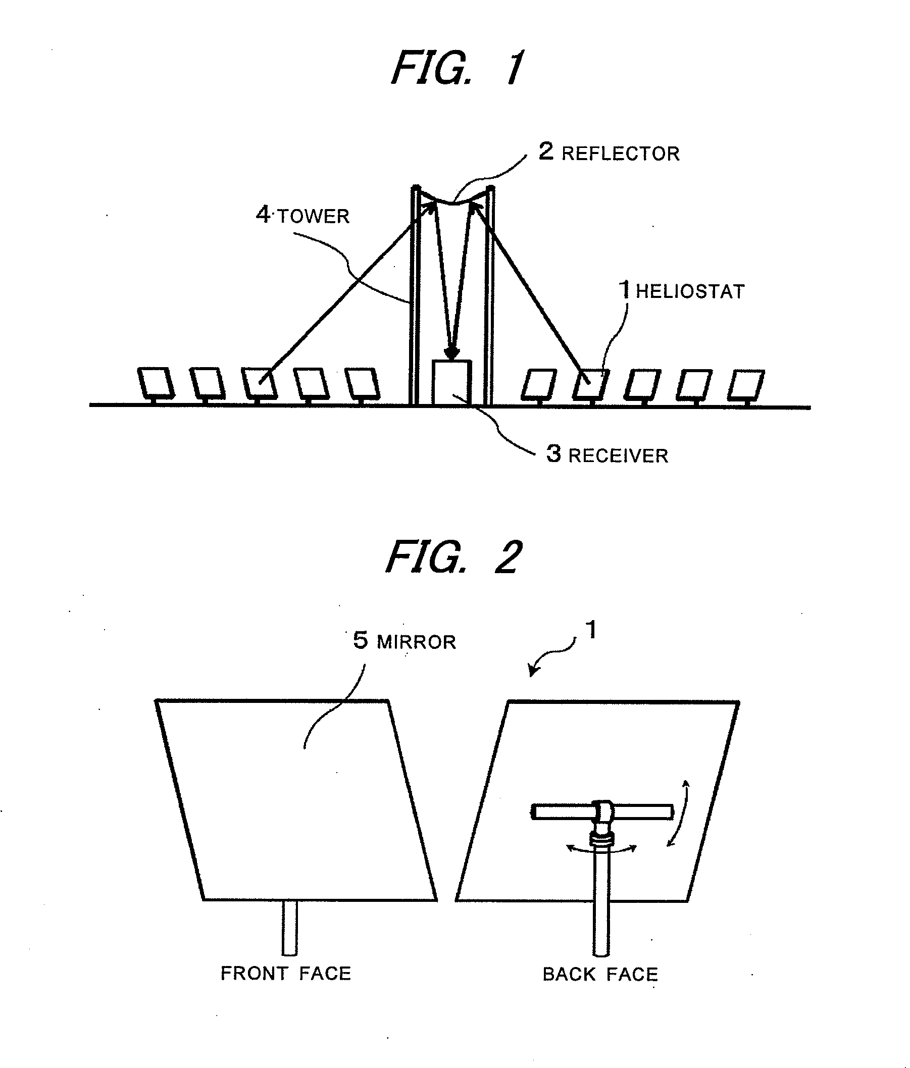
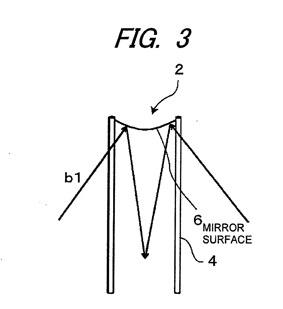
[0037]A multi-tower beam-down light collecting system is a system in which, in a field where a plurality of beam-down light collecting towers are present, light primarily reflected by heliostats around each tower is secondarily reflected by a reflector on a top part of the tower to collect the light on a receiver on the ground. FIG. 1 shows a basic structure of a beam-down light collecting system as a solar light collecting system using heliostats. In FIG. 1, the beam-down light collecting system is configured by a combination of a group of heliostats 1, 1, . . . dispersedly arranged on the ground and a tower 4 including a reflector 2 and a receiver 3. The reflector 2 is a reflection mirror disposed in a position of an upper focus at a top part of the tower 4, and the receiver 3 is disposed in a position of a lower focus at a bottom part of the tower 4 (on the ground) so as to face the reflector 2. The beam-down light collecting system is a system in which the sunlight p...


PUM


Abstract

It enhances heat collecting efficiency of sunlight received by heliostats. It is a solar light collecting method in a multi-tower beam-down light collecting system, including a tower selection. The multi-tower beam-down light collecting system is a system in which, in a field where a plurality of beam-down light collecting towers are present, light primarily reflected by heliostats 1 around each tower 4 is secondarily reflected by a reflector 3 at a top part of the tower 4 and is collected on a receiver 3 on the ground, and the tower selection is a process in which, assuming that the heliostat 1 in a given position receives sunlight and reflects the sunlight toward each of optionally selected two of the towers 4, 4, a light receiving quantity on the receiver 3 of each of the towers 4 is compared, and one of the towers 4 in which the light receiving quantity is relatively large is selected to reflect the sunlight toward the one of the towers 4.

Description

TECHNICAL FIELD[0001]The present invention relates to a method of enhancing light collecting efficiency of solar energy in a multi-tower beam-down light collecting system.BACKGROUND ART[0002]Of renewable natural energy, solar thermal energy is very promising as energy to replace fossil fuel, owing to its abundant potential quantity (potential quantity of energy resource). The intensity of solar thermal energy, though it varies depending on locations, is about 1 kW / m2. Thermal energy of sunlight can be sufficiently utilized as an energy source for operating a thermochemical reaction plant, a power generation plant or the like. In order to utilize the solar thermal energy as an energy source, it is required to be efficiently converted into chemical energy or electric energy, and in order to enhance the conversion efficiency, it is required to efficiently collect the sunlight.[0003]The position of the sun relative to a point on the ground changes over time due to the rotation of the ea...

Claims


Application Information

Patent Timeline
IPC IPC(8): F24J2/18F24J2/38F24S23/79F24S50/20
CPCF24J2/07F24J2/18F24J2/40F24J2/5417Y02E10/41F24J2002/385G02B7/1824H01L31/052F24J2002/1076F24S23/79F24S20/20F24S2023/87F24S30/45F24S2050/25F24S50/00Y02E10/40
Inventor YUASA, MINORUHASUIKE, HIROSHITAMAURA, YUTAKA
Owner COSMO OIL CO LTD
Why Eureka
Try Eureka