Transmissive organic light emitting diode and transmissive lighting device using the same

Inactive Publication Date: 2011-10-27
ELECTRONICS & TELECOMM RES INST
View PDF4 Cites 72 Cited by
  • Summary
  • Abstract
  • Description
  • Claims
  • Application Information

AI Technical Summary

Benefits of technology

[0016]The present invention is directed to an organic light emitting diode (OLED) including a light extraction enhancing layer capable of changing a path of light generated from an organic emission layer to enhance light extraction efficiency of the OLED and a transmissive lighting device using the same.
[0017]One aspect of the present invention provides a transmissive OLED including a transparent anode formed on a substrate, an organic emission layer formed on the transparent anode, a transparent cathode formed on the organic emission layer, and a light extraction enhancing layer formed on the transparent cathode, changing a path

Problems solved by technology

The incandescent lamps have low efficiency and a short life span and the fluorescent lamps include a heavy metal such as mercury, lead, etc.
However, as described above, although the conventional OLED includes the t

Method used


Image

  • Transmissive organic light emitting diode and transmissive lighting device using the same
  • Transmissive organic light emitting diode and transmissive lighting device using the same
  • Transmissive organic light emitting diode and transmissive lighting device using the same

Examples


Embodiment Construction

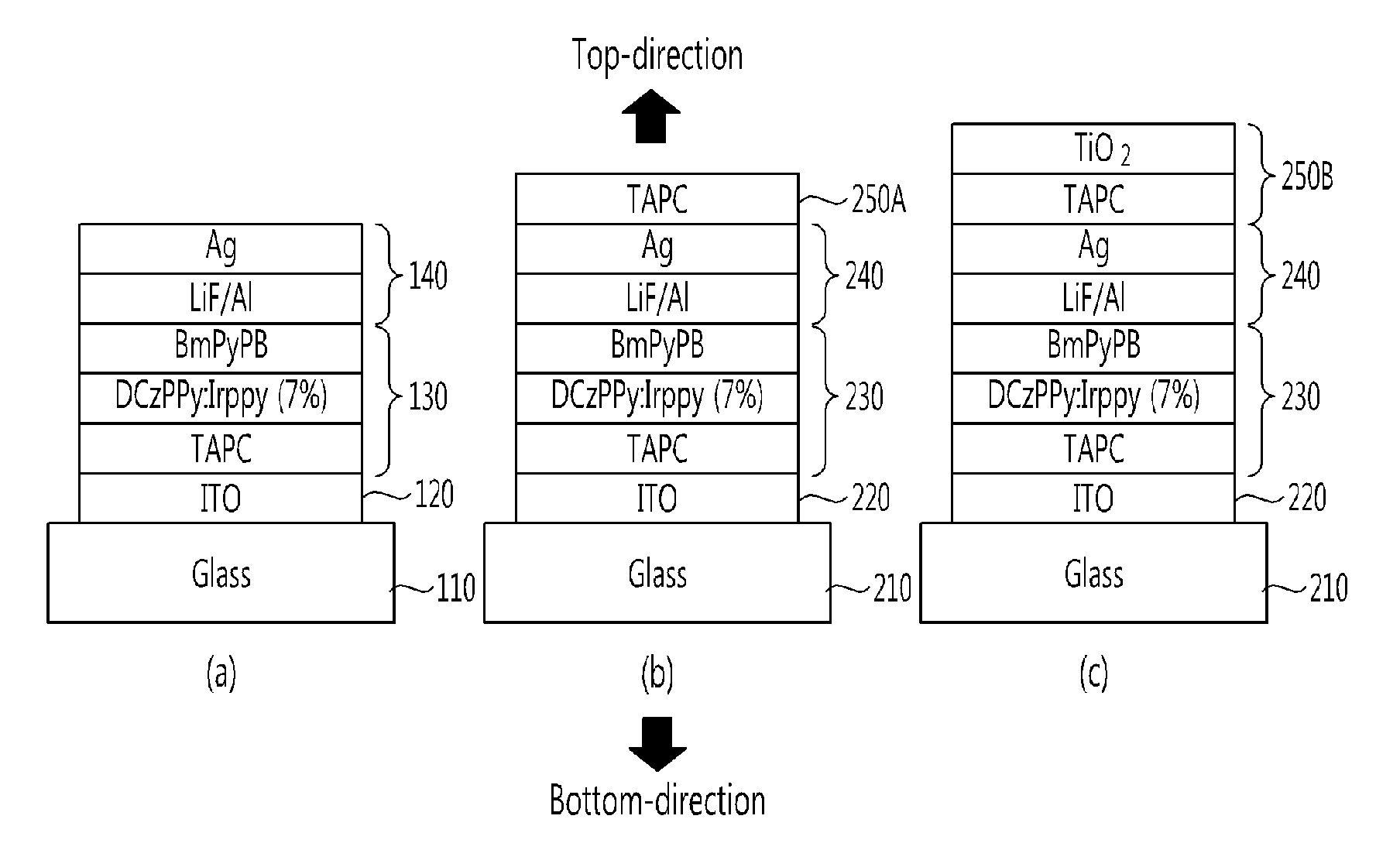
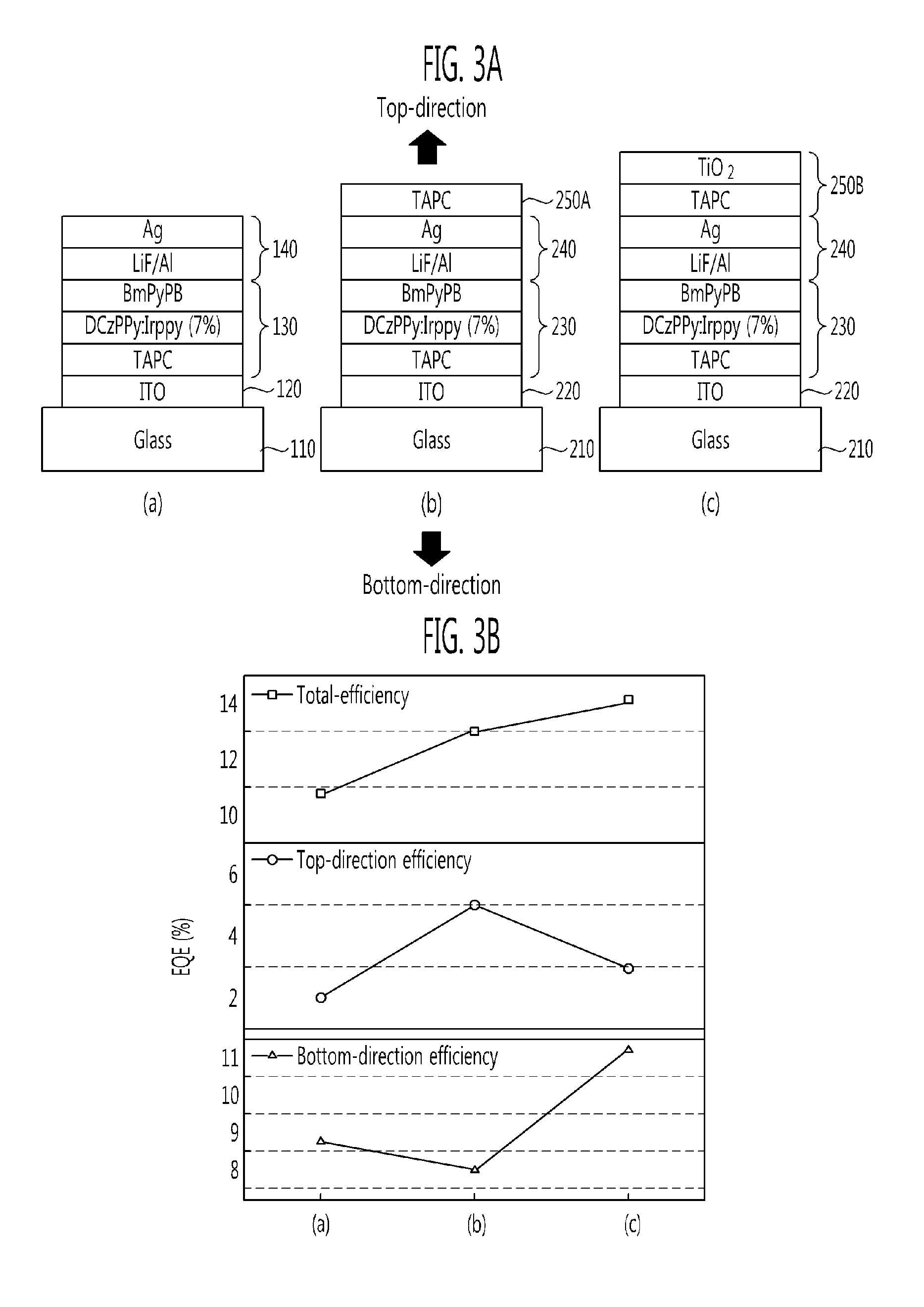
[0026]The present invention will be described more fully hereinafter with reference to the accompanying drawings, in which exemplary embodiments of the invention are shown. This invention may, however, be embodied in different forms and should not be construed as limited to the embodiments set forth herein. In drawings, portions unrelated to description will be omitted to distinctly describe the present invention and similar reference numerals are labeled to similar portions throughout the specification.

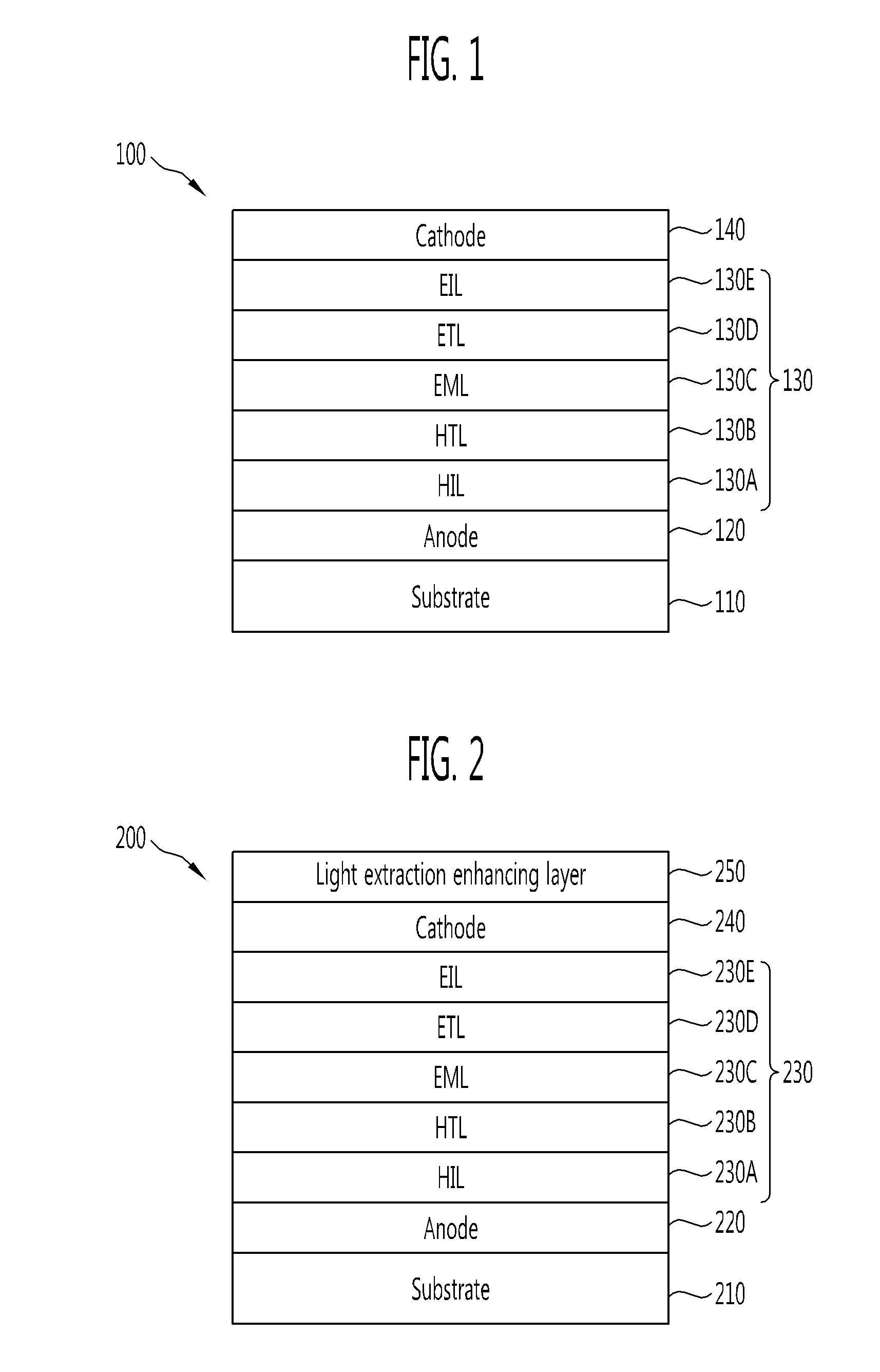
[0027]FIG. 2 is a cross-sectional view illustrating the structure of a transmissive organic light emitting diode (OLED) according to embodiments of the present invention.

[0028]organic emission layer 230, and a light extraction enhancing Referring to FIG. 2, an OLED 200 includes a transparent anode 220 formed on a substrate 210, an organic emission layer 230 formed on the transparent anode 220, a transparent cathode 240 formed on the layer 250 formed on the transparent cathode and con...


PUM


Abstract

A transmissive organic light emitting diode (OLED) with improved external light efficiency and a transmissive lighting device including the same are provided. The OLED includes a transparent anode formed on a substrate, an organic emission layer formed on the transparent anode, a cathode formed on the organic emission layer, and a light extraction enhancing layer formed on the transparent cathode, and configured to change a path of light generated from the organic emission layer to enhance light extraction efficiency of the OLED. The external light extraction efficiency is enhanced in both-sided or single-sided emission of the OLED and the external light extraction efficiencies of bottom and top surfaces of the OLED are selectively or simultaneously enhanced. An external light extraction ratio between the bottom and top surfaces in both-sided emission is controlled.

Description

CROSS-REFERENCE TO RELATED APPLICATION[0001]This application claims priority to and the benefit of Korean Patent Application No. 10-2010-0037777, filed Apr. 23, 2010, the disclosure of which is incorporated herein by reference in its entirety.BACKGROUND[0002]1. Field of the Invention[0003]The present invention relates to a transmissive organic light emitting diode (OLED) and a transmissive lighting device including the same, and more specifically, to a transmissive OLED with improved external light efficiency and a transmissive lighting device including the same.[0004]2. Discussion of Related Art[0005]Conventionally, incandescent lamps or fluorescent lamps have mostly been used as lighting devices. The incandescent lamps have low efficiency and a short life span and the fluorescent lamps include a heavy metal such as mercury, lead, etc.[0006]Accordingly, studies on organic light emitting diodes (OLEDs) as next generation lighting devices have been actively conducted. The OLEDs are e...

Claims


Application Information

Patent Timeline
IPC IPC(8): H01L51/52
CPCH01L51/0059H01L51/0067H01L51/0072H01L2251/5323H01L51/5262H01L2251/308H01L51/0085H10K85/631H10K85/654H10K85/342H10K85/6572H10K2102/3031H10K2102/103H10K50/858H10K50/85
Inventor LEE, JOO WONCHU, HYE YONGLEE, JONG HEELEE, JEONG IK
Owner ELECTRONICS & TELECOMM RES INST
Why Eureka
Try Eureka