Motor stator and manufacturing method of motor stator

a manufacturing method and motor stator technology, applied in the manufacture of stator/rotor bodies, windings, dynamo-electric components, etc., can solve the problems of reducing the winding space factor of the resulting v- and w-phase coils, not being able to insert many wires, and reducing the efficiency of the motor, so as to reduce the volume of the coil, increase the motor efficiency, and suppress the coil resistance and copper loss

Inactive Publication Date: 2011-10-27
HONDA MOTOR CO LTD
View PDF8 Cites 19 Cited by
  • Summary
  • Abstract
  • Description
  • Claims
  • Application Information

AI Technical Summary

Benefits of technology

[0020]One or more embodiments of the invention provide a motor stator which can decrease the coil volume so as to suppress the coil resistance and copper loss to thereby increase the mot

Problems solved by technology

As this occurs, it is not possible to insert many wires in the slots for the other phases, which decreases the winding space factors of the resulting V- and W-phase coils.
As a result of this, the copper loss becomes large, leading to a problem that the motor efficiency is decreased.
However, the coils 1112, 1113, 1114 are not fixed to the stator core 1110, and therefore, after the wires 1115 are wound around, a lacing treatment and a varnish treatment need to be applied to the wires 1115, which requires many man hours in manufacturing a stator, leading to a problem that the manufacturing costs are increased.
As a result of this, the coil volume which is wasteful is increased, and not only are the motor weight and the coil resistance increased, but also the copper loss is increased, leading to a problem that the motor efficiency is decreased.
In addition, the increase in size of the motor is also problematic, there exists room for improvement.
Furthe

Method used


Image

  • Motor stator and manufacturing method of motor stator
  • Motor stator and manufacturing method of motor stator
  • Motor stator and manufacturing method of motor stator

Examples


first embodiment

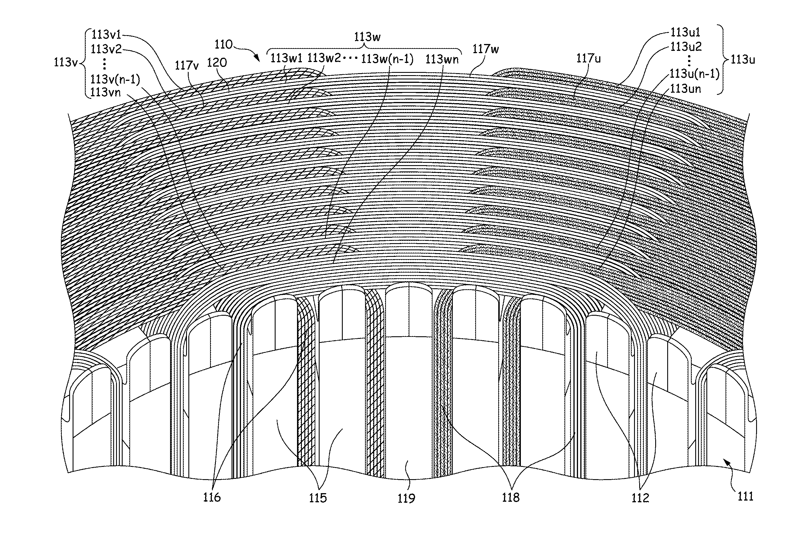
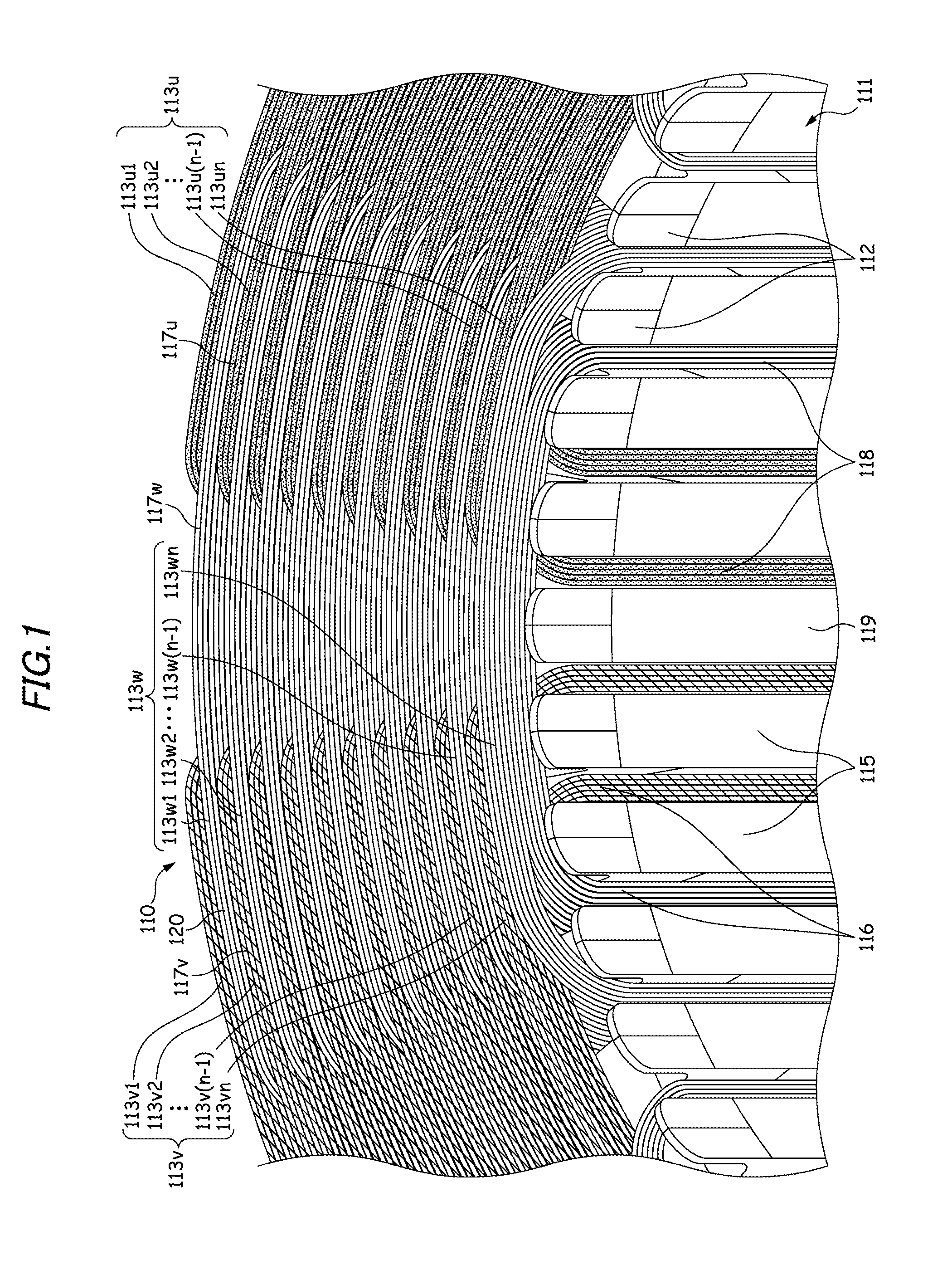
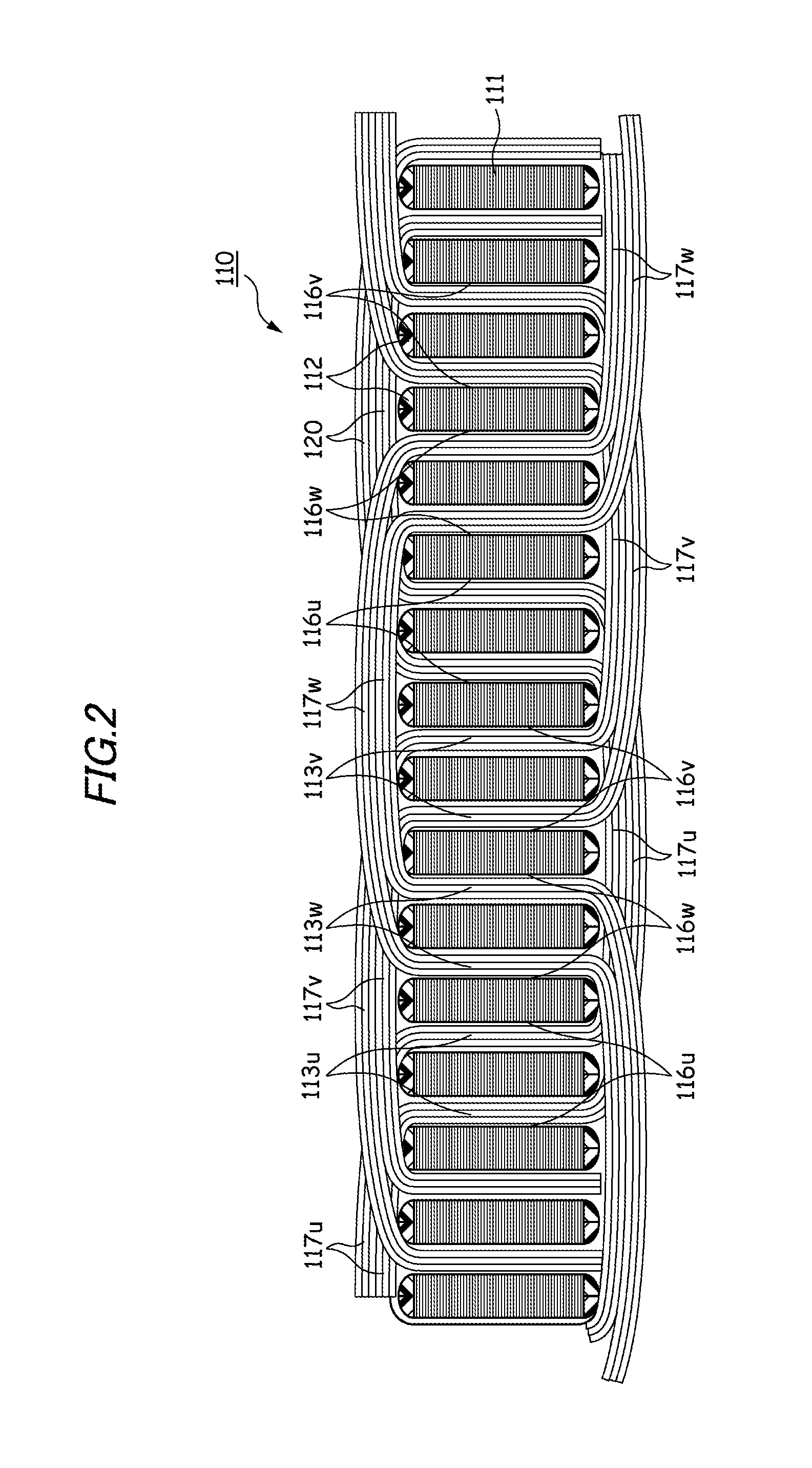
[0063]As is shown in FIG. 1, a motor stator 110 according to a first embodiment is a three-phase, eight-pole, distributed-winding stator and includes a stator core 111, insulation members 112, and coils 113 (a U-phase coil 113u, a V-phase coil 113v, and a W-phase coil 113w). The stator core 111 is made up of, for example, a plurality of pressed silicon steel sheets which are stacked one on another and includes 148 tees 115 and 148 slots 116 which are each formed between adjacent tees 115, 115. In addition, a motor is an inner rotor type motor, and an opening portion 118 of the slot 116 is opened in an inner circumferential surface 119 of the stator core 111.

[0064]A plurality of insulation members 112 are inserted into each slot 116 from both axial ends of the stator core 111 so as to cover an inner surface of the slot 116. Each insulation member 112 is formed of resin material through injection molding and has electric insulation properties and appropriate elasticity. The insulation...

example

[0097]Table 1 shows a comparison made between the motor stator according to the embodiment which is manufactured by the method shown in FIG. 7(a) and the motor stator which is manufactured by the conventional method shown in FIG. 7(b). Note that in Table 1, values given to the motor stator of the embodiment with respect to respective items indicate ratios to values given to the conventional motor stator when the latter values are regarded as 100.

TABLE 1ConventionalStator of theStatorEmbodimentAdvantageWire Weight10087WeightReductionCopper Loss10094EfficiencyIncreaseCoil End10085Size ReductionPortionSectional Area

[0098]As is shown in Table 1, compared with the conventional motor stator, in the motor stator according to the embodiment, the wire weight and the copper loss are reduced to 87% and 94%, respectively. By these reductions, not only is the overall weight of the motor reduced, but also the motor efficiency is increased. In addition, the sectional area of the coil end portion i...

second embodiment

[0099]As is shown in FIG. 12, a motor stator 10 according to a second embodiment of the invention is a three-phase, eight-pole, distributed-winding stator and includes a stator core 11, insulation members 12, and coils 13 (a U-phase coil 13u, a V-phase coil 13v, and a W-phase coil 13w). The stator core 11 is made up of, for example, a plurality of pressed silicon steel sheets which are stacked one on another and includes 48 tees 15 and 48 slots 16 which are each formed between adjacent tees 15, 15. An opening portion 18 of the slot 16 is opened in an inner circumferential surface 19 of the stator core 11.

[0100]A plurality of insulation members 12 are inserted into each slot 16 from both axial ends of the stator core 11 so as to cover an inner surface of the slot 16. Each insulation member 12 is formed of resin material through injection molding and has electric insulation properties and appropriate elasticity. The insulation members 12 are intended to establish electric insulation b...


PUM

PropertyMeasurementUnit
Lengthaaaaaaaaaa
Fractionaaaaaaaaaa
Diameteraaaaaaaaaa

Abstract

A motor stator (10) is provided with a stator core (11) having a plurality of slots (16), insulation members (12) which are disposed in the plurality of slots, and coils of a plurality of phases (13) which are respectively formed by distributed-winding wires (20) in prescribed slots of the plurality of slots disposed spaced apart at intervals of a predetermined number of slots via the insulation members. The wires are disposed within the insulation members in a condition that tensions are applied to the wires. The stator core, the insulation members and the coils are physically fixed together by the tensions of the wires.

Description

BACKGROUND OF THE INVENTION[0001]1. Field of the Invention[0002]The present invention relates to a stator of a motor which is mainly used as a power source for an electric vehicle or a hybrid vehicle and in which wires are distributed-wound, and a manufacturing method thereof.[0003]2. Related Art[0004]Conventionally, stators of distributed-winding motors are manufactured by using a series-winding method in which coils are formed by series-winding wires relative to a stator core or an insert method in which coils which are formed in advance by winding wires are inserted into slots in a stator core.[0005]As the series-winding method, there is disclosed a method and apparatus for winding wires of a stator core. In the method and apparatus, a former detachable installation and replacement portion, a winding arm drive portion, an inspection portion and an interphase insulator installation portion are sequentially disposed around the circumference of a stator core held by a holder, and a ...

Claims


Application Information

Patent Timeline
IPC IPC(8): H02K3/28H02K3/34H02K15/02
CPCH02K3/345Y10T29/49009H02K15/085H02K15/068
Inventor HIRAGA, KAZUHITOOMAGARI, KENICHISHIBATA, TAKUMIKAKEMA, MASAHITOMATSUOKA, YOSHIHISAOKAMURA, MITSUHIRONINOMIYA, EIJIYANAGISAWA, TAKESHI
Owner HONDA MOTOR CO LTD
Why Eureka
Try Eureka