
Method of igniting a lamp, controller for a lamp, and a lamp controlled by a controller

a technology of lamp and controller, which is applied in the direction of energy-saving lighting, pulse technique, sustainable buildings, etc., can solve the problems of insufficient capacitive mode detection, damage to the fet, and relatively slow frequency control which is conventionally used for capacitive mode detection

Inactive Publication Date: 2011-10-27
NXP BV
View PDF4 Cites 0 Cited by
  • Summary
  • Abstract
  • Description
  • Claims
  • Application Information

AI Technical Summary

Benefits of technology

[0015]Since the method of this aspect of the invention provides control in response to a predetermined reference signal, the method provides for flexibility of control.
[0016]Preferably, the step of increasing the slope of the saw-tooth generator comprises increasing the slope by a factor of more than 2. This enables the circuit to protect against capacitive mode operation.
[0017]In embodiments the slope of the sawtooth generator is increased immediately on detection of any magnetic saturation in the coil. The magnetic saturation arises due to the current through the coil, and the term ‘current saturation’ will hereinafter be used interchangeably. Alternatively, the slope of the sawtooth generator is increased on detection of current saturation in the coil by between 25% and 75%, or by between 75% and 125% even on detection of current saturation in the coil by more than 125%, and preferably within a range of 25%-50%, thereby ensuring the current does not peak too early or sharply. These embodiments thus provide for a degree of flexibility of control.
[0020]In embodiments, the first switch is opened in response to the output of the saw-tooth exceeding the reference signal. Alternatively or in addition, the saw-tooth generator may be reset in response to an ending of current saturation in the coil. The first switch may then be opened either directly or after a delay, in response to the ending of the current saturation. A post peak current reset facility may thereby be provided, which can provide the designer or user with a further degree of control.

Problems solved by technology

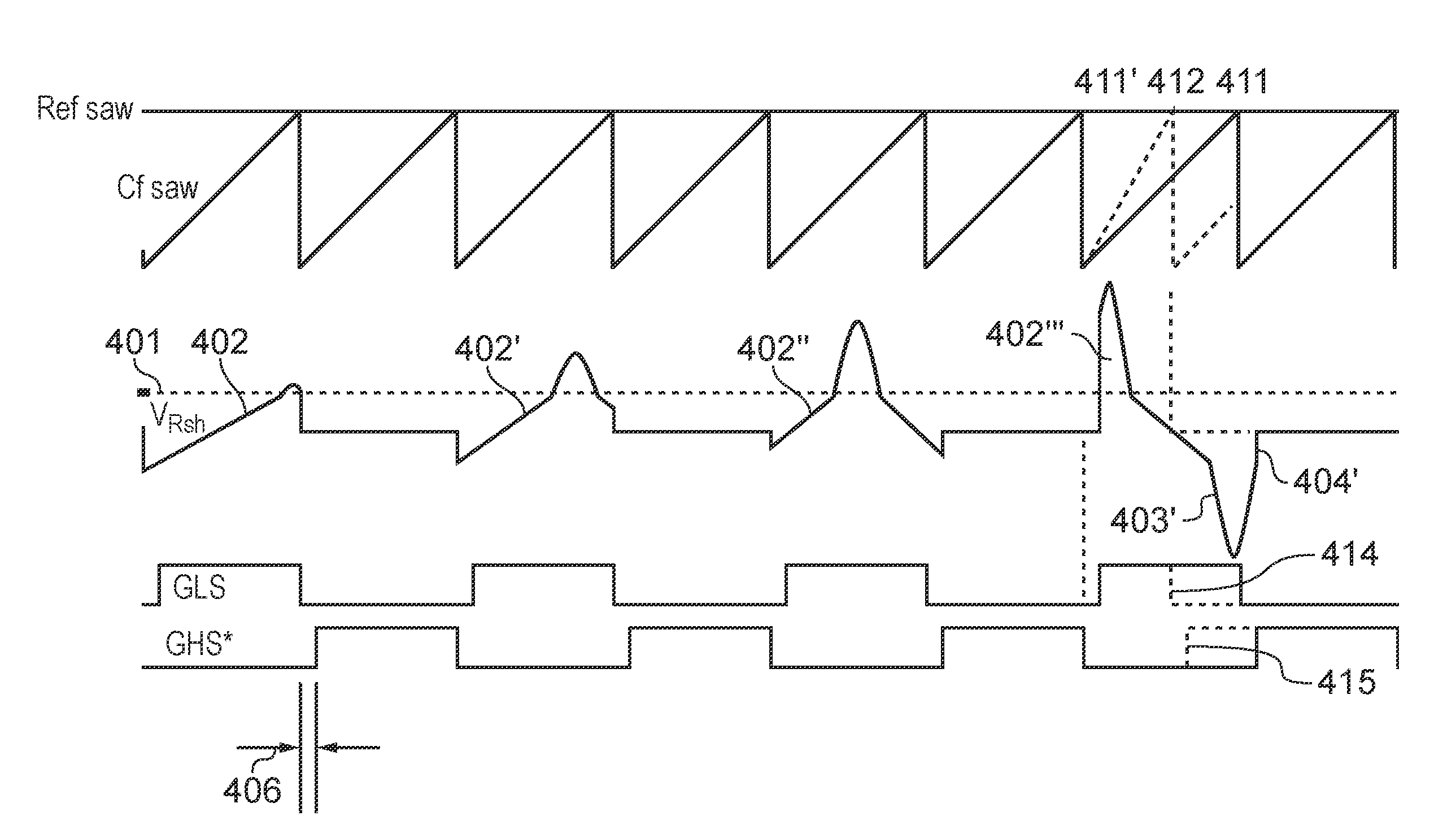
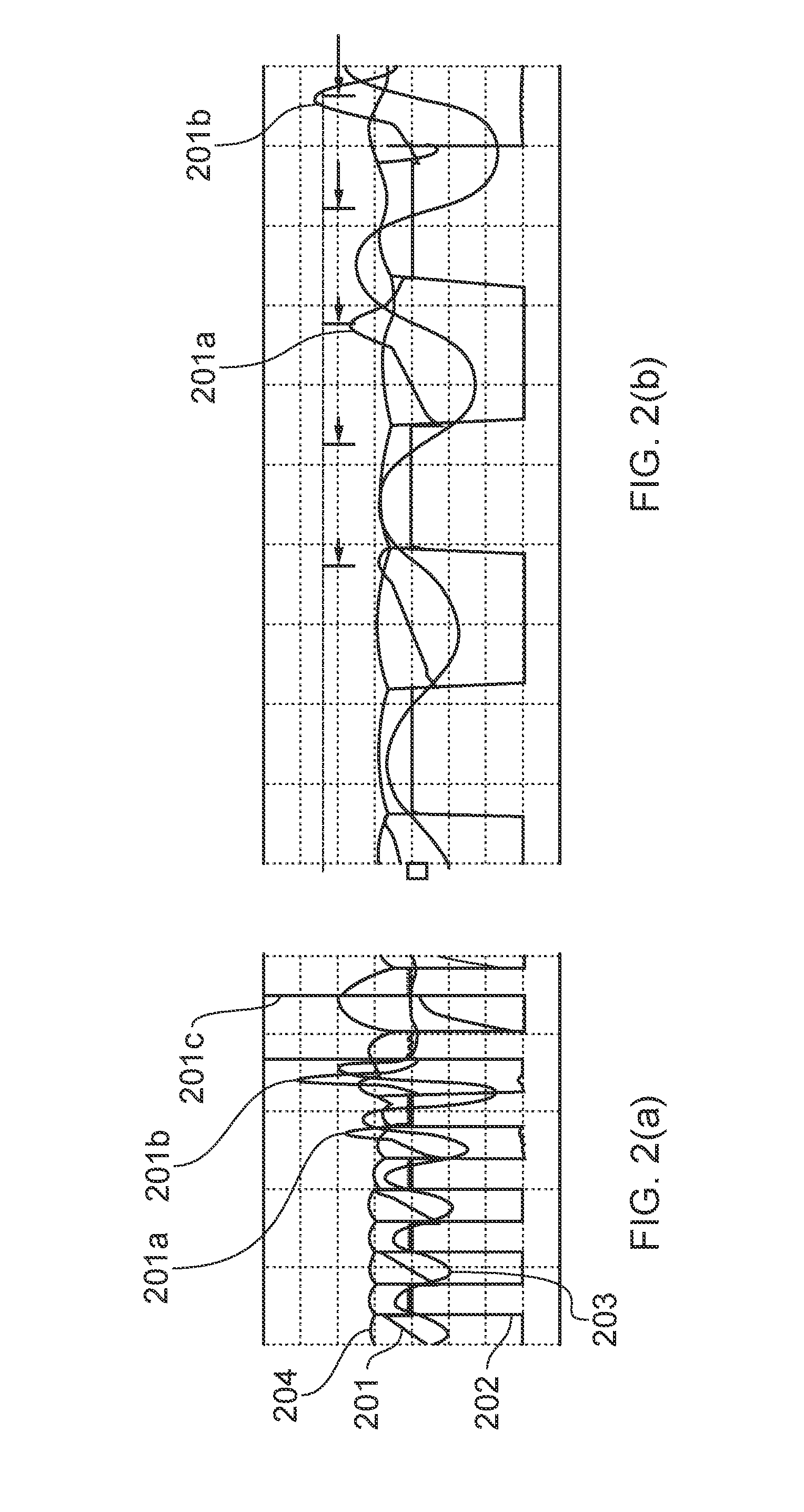
This can result in a reduced current slope, and within just a few cycles, the slope of the current can become negative, resulting in capacitive mode operation.
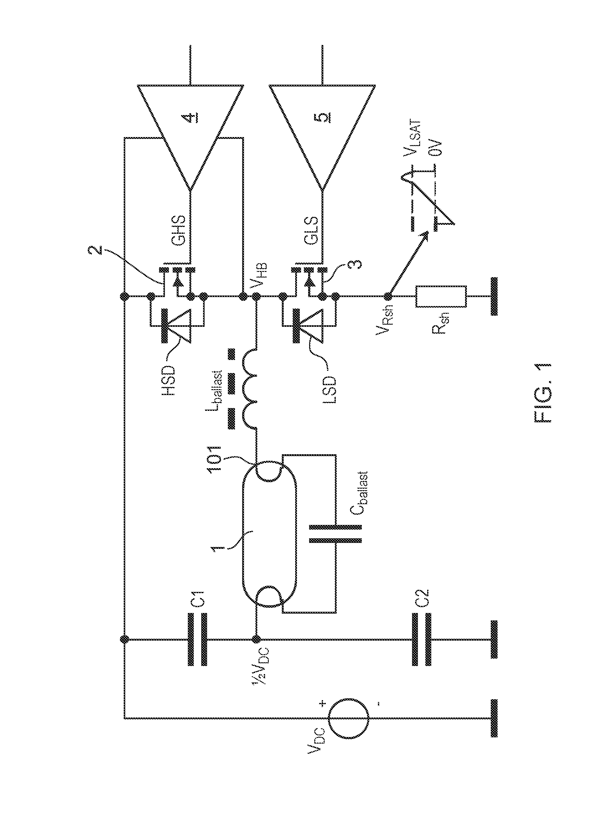
The resulting hard switching, in which HSS switch 2 is closed whilst the body diode of the LSS switch 3 is conducting to provide reverse recovery, can be damaging to the FET, and can even cause it to fail.
Since the saturation of the lamp coil can result in a fast change to the resonant frequency, and thus a change from inductive mode to capacitive mode within a few cycles, it is necessary to create a frequency control that reacts very quickly, and the relatively slow frequency control which is conventionally used for capacitive mode detection is not adequate.
This would result in a much steeper rate of change of the ignition the voltage (ΔV / ΔT), and a consequent short faster rise in the ignition amplitude.

Method used


Image

  • Method of igniting a lamp, controller for a lamp, and a lamp controlled by a controller
  • Method of igniting a lamp, controller for a lamp, and a lamp controlled by a controller
  • Method of igniting a lamp, controller for a lamp, and a lamp controlled by a controller

Examples


Embodiment Construction

[0035]FIG. 3 shows a simplified schematic of a conventional half-bridge driving a compact fluorescent lamp with a controller using a sawtooth oscillator. In the figure, a conventional sawtooth oscillator 301 comprises a current source Icf, which charges a capacitor Cf. The capacitor voltage increases until it exceeds the first predetermined reference voltage Vsaw, the comparison being made in comparator 302. Once the voltage exceeds Vsaw, switch 304 is opened to discharge the capacitor, the discharge period τ being set by delay logic 303. The output from the sawtooth generator is directed to the divide-by-two logic 308, in order to halve its frequency, and thence to logic 307 to control the low side switch driver 5. A second output from the driver logic 307 is directed to a level shift 306 and thence to the high side switch driver 4.

[0036]A timing diagram for the circuit of FIG. 3 is shown in FIG. 4, during an ignition phase. FIG. 4 shows, in solid lines starting at the bottom, the ...


PUM


Abstract

A method of igniting a lamp is disclosed. The lamp may be a compact fluorescent lamp. The method is directed in particular to reducing or eliminating hard-switching of half-bridge switches driving a lamp. The method operates by reducing the on-time of at least one of the switches, in response to saturation of the ballast inductor. The method can operate immediately upon saturation of the ballast inductor, or allow a predetermined level of saturation. The method operates by increasing the slope of the sawtooth timing circuit.

Description

FIELD OF THE INVENTION[0001]This invention relates to a method of igniting a lamp. Such a lamp may be, for example, a compact fluorescent lamp. It further relates to a circuit arrangement for a lamp, and to a lamp such as a fluorescent lamp or a compact fluorescent lamp, including such a circuit arrangement.BACKGROUND OF THE INVENTION[0002]With an increasing drive towards energy-efficient lighting, lamps based on fluorescence rather than incandescence are increasingly important. However, in many situations, a commercially viable product must be similar in the size or form to existing incandescent lightbulbs. Compact fluorescent lamps (CFL) have been developed to meet such a need.[0003]The ignition of such lamps requires an electrical supply with significantly different characteristics to that of the supply during normal operation. In order to meet such requirements, such lamps are often supplied with a ballast coil or inductor in series between the lamp and a switched power supply, ...

Claims


Application Information

Patent Timeline
IPC IPC(8): H05B37/02
CPCH03K17/165H03K17/6871Y02B20/19H05B41/2856Y02B20/186H05B41/2828Y02B20/00
Inventor VAN ELK, HENRICUS THEODORUS PETRUS JOHANNESKLEINPENNING, JEROEN
Owner NXP BV
Learn More