Light source module, lighting apparatus, and illumination device using the same

a technology of light source module and illumination device, which is applied in the direction of electric variable regulation, process and machine control, instruments, etc., can solve the problems of electrical shock, heat generation, failure or short life span attributable to excessive current, etc., and achieve the effect of safely installing and lighting up the light source modul

Inactive Publication Date: 2011-10-27
PANASONIC CORP
View PDF5 Cites 47 Cited by
  • Summary
  • Abstract
  • Description
  • Claims
  • Application Information

AI Technical Summary

Benefits of technology

[0016]In view of the above, the present invention provides a light source module and a lighting apparatus that can deal with the advancements in the technology of LEDs and that can be safely installed in a general illumination device for a fluorescent lamp, and an illumination device using the same.
[0020]In accordance with the present invention, characteristic information corresponding to the electrical characteristics of each LED can be previously set in the characteristic setting unit and, therefore, the advancements made in the technology of LEDs can be handled. In accordance with another aspect of the present invention, a lighting apparatus which is capable of stably lighting up the light source module can be implemented. In accordance with another aspect of the present invention, the light source module can be safely installed in a general illumination device for a fluorescent lamp.

Problems solved by technology

However, by applying a current of 0.3 A to a LED having an output current of 0.2 A, the problem of abnormal generation of heat, a failure or a short life span attributable to excessive current is caused.
However, for a light source using LEDs, when, for example, the anode side is connected to the first pin base and the cathode side is connected to the second pin base, there is a worry over an electric shock if the electrodes of the first pin base are inserted into a socket and then user's contact with an electrode of the second pin base occurs upon the above-described replacement of the lamp.
However, since it is necessary to install a data retention unit (a microcomputer or the like) and a control power source circuit for the data retention unit in each LED module, the configuration of the LED module is complicated, the cost of the LED module is increased, and the control power source circuit for the data retention unit installed in each LED module is difficult to configure.
The former method generates power loss because the lighting apparatus needs to be operated while the LED module is not being connected.
The latter method causes the wiring between the lighting apparatus and the LED module to be complicated.
Since the conventional technology does not provide a specific technology for configuring an electrical connection nor a specific technology for the structure of the LED module, there is a worry over the electric shock when the LED module is replaced.

Method used


Image

  • Light source module, lighting apparatus, and illumination device using the same
  • Light source module, lighting apparatus, and illumination device using the same
  • Light source module, lighting apparatus, and illumination device using the same

Examples


embodiment 1

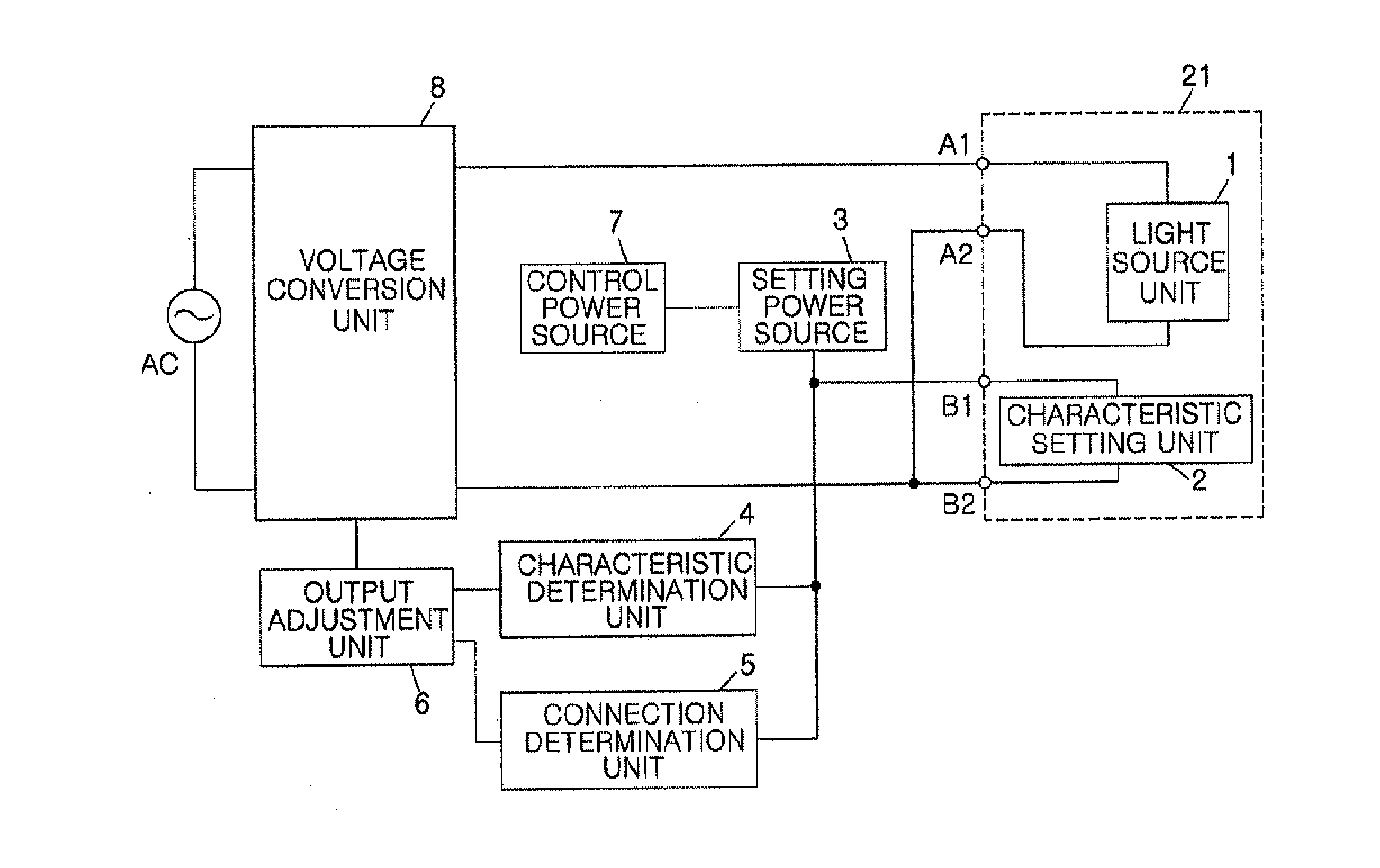
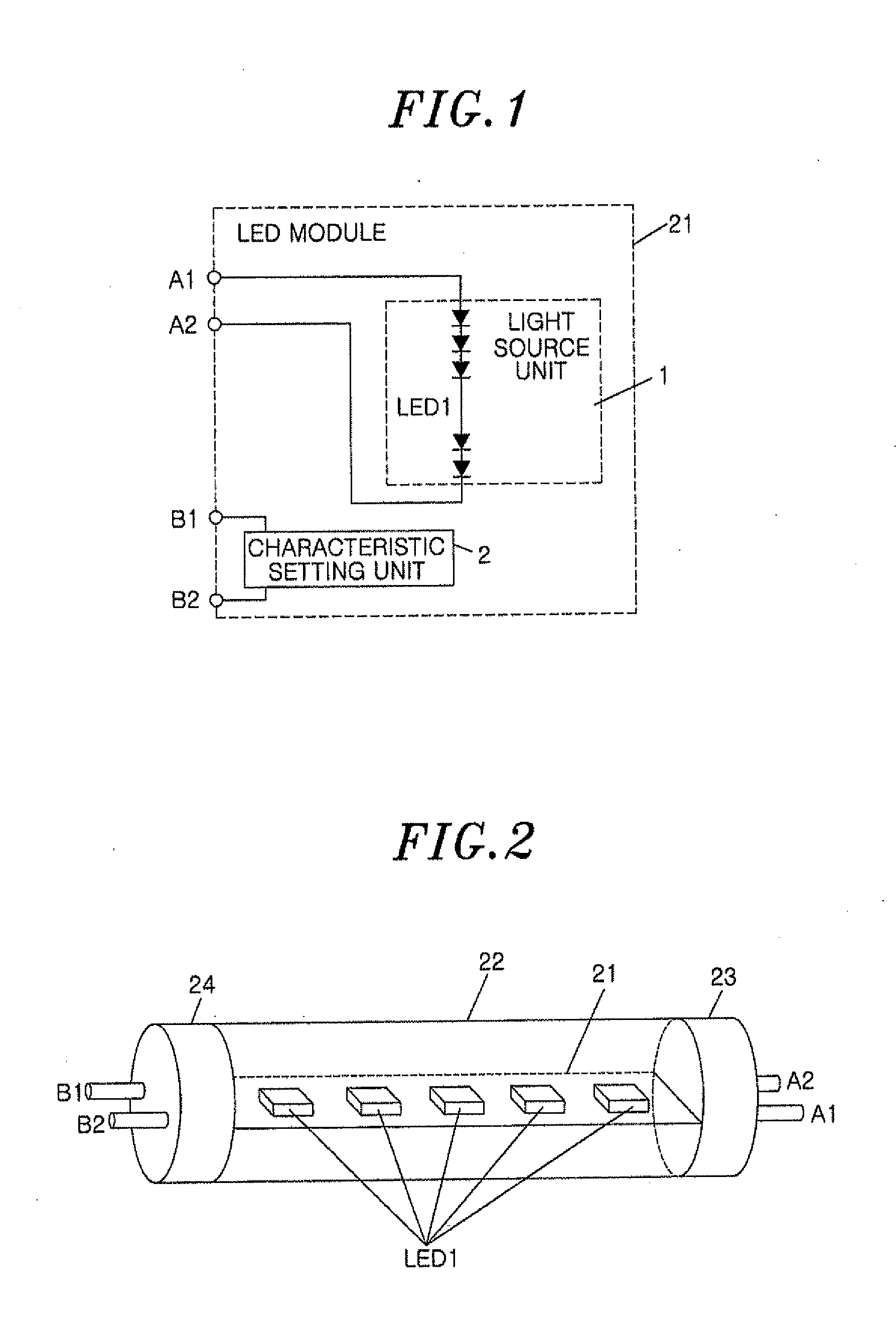
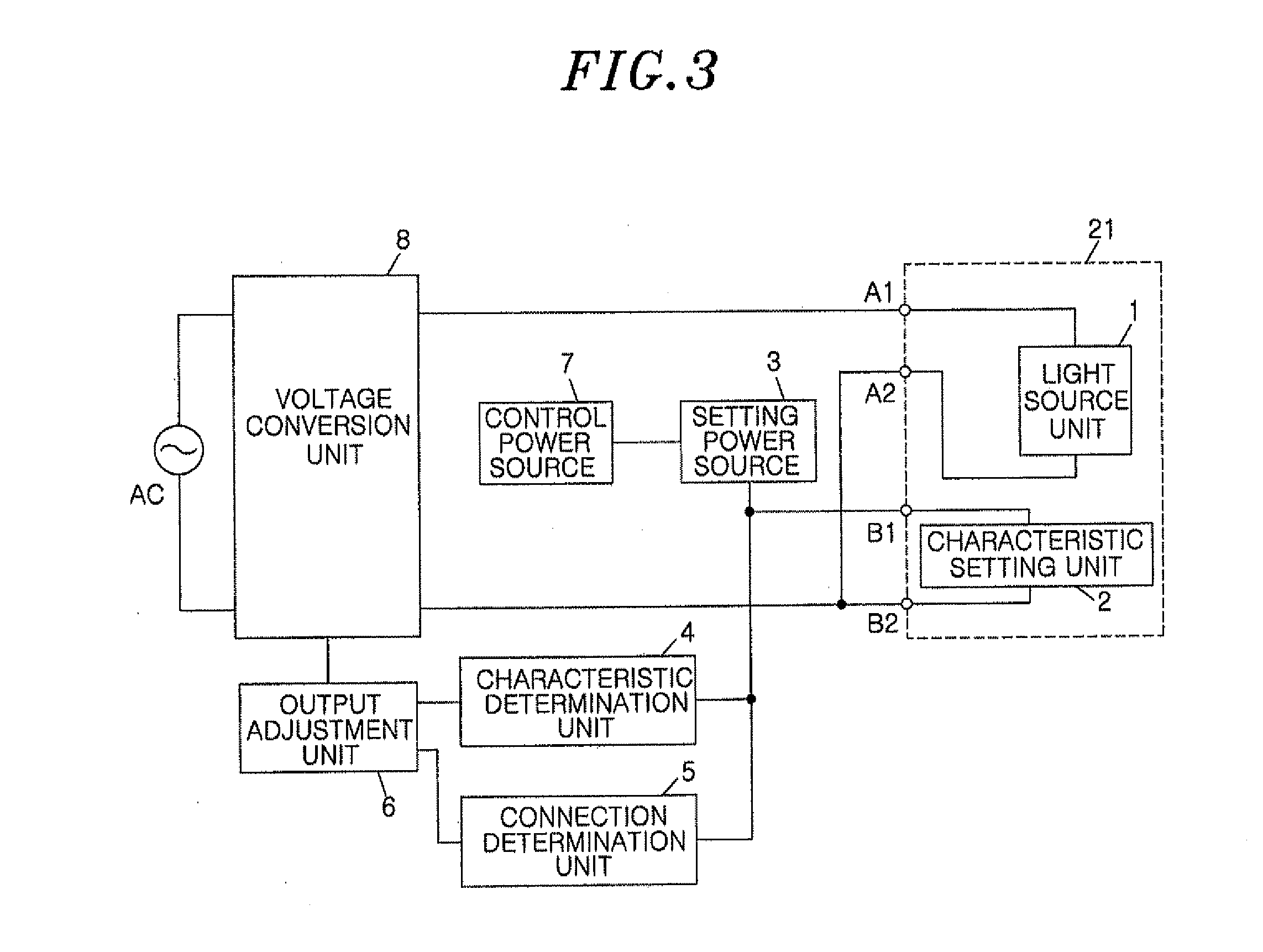
[0039]FIG. 1 is a diagram showing a circuit configuration of an LED module in accordance with a first embodiment of the present invention. As shown in FIG. 1, an LED module 21 includes a light source unit 1 configured such that a plurality of light-emitting diodes (LEDs) are connected in series to each other and a characteristic setting unit 2 for setting characteristic information of the LEDs LED1, for example, information corresponding to a target current value.

[0040]The anode side of the light source unit 1 is connected to a connection terminal A1 which is selectively and electrically connected and disconnected to a lighting apparatus provided outside the LED module 21, and the cathode side of the light source unit 1 is connected to a connection terminal A2. The characteristic setting unit 2 is connected between connection terminals B1 and B2.

[0041]FIG. 2 shows an example of a structure of the LED module 21. As shown in this drawing, one or more rectangular substrate on which the...

embodiment 2

[0071]FIG. 10 is a diagram showing a circuit configuration of an LED module in accordance with a second embodiment of the present invention. The configuration of a lighting apparatus according to the present embodiment is the same as that of the first embodiment. The LED module of the present embodiment is different from that of the first embodiment in that connection terminals A1 and A2 are connected to the input terminal of a rectifier DB1, the positive output side of the output terminal of the rectifier DB1 is connected to the anode side of a light source unit 1, and the negative output side of the output terminal of the rectifier DB1 is connected to the cathode side of the light source unit 1. Furthermore, with regard to a characteristic setting unit 2, control power supplied from a setting power source 3 constituting part of the lighting apparatus to the connection terminals B1 and B2 is supplied to the characteristic setting unit 2 via a rectifier DB2.

[0072]Although the detail...

embodiment 3

[0076]FIG. 12 shows a circuit configuration of an LED module in accordance with a third embodiment of the present invention. The basic configuration of the LED module of this embodiment is almost the same as that of the second embodiment. However, the detailed configuration of a contained characteristic setting unit 2 is different from that of the second embodiment in that it includes a resistor R6.

[0077]A lighting apparatus is configured almost the same as that of the first embodiment (shown in FIG. 3), as shown in the block diagram of FIG. 13. As seen from FIG. 13, the difference resides in that the internal wiring of the illumination device is configured to connect the LED module 21a and the LED module 21b in series to each other.

[0078]The output terminal of the voltage conversion unit 8 of the lighting apparatus is connected to the connection terminal A1 of the LED module 21a and the connection terminal A2 of the LED module 21b, and the connection terminal A2 of the LED module 2...


PUM


Abstract

A light source module includes: a light source unit including a plurality of light-emitting diodes (LEDs) electrically connected to each other; a characteristic setting unit for setting characteristic information on electrical characteristics of the LEDs; a first pin base having a first electrode and a second electrode; and a second pin base having a third electrode and a fourth electrode, wherein a direct current (DC) voltage supplied from a lighting apparatus is applied between the first electrode and the second electrode or between the third electrode and the fourth electrode, a constant voltage is supplied to an anode side of the LEDs of the light source unit, and the characteristic setting unit is connected between the first and second electrodes and / or between the third and fourth electrodes.

Description

FIELD OF THE INVENTION[0001]The present invention relates to a light source module that uses light-emitting diodes (LEDs) as a light source, a lighting apparatus for lighting up the light source module, and an illumination device using the same.BACKGROUND OF THE INVENTION[0002]So far, fluorescent lamps have been the main light sources used for illumination, and illumination devices which perform high frequency lighting using inverter lighting apparatuses have become widely popularized. Recently, LEDs have been attracting attention as being electrical light sources other than a discharge lamp which is represented as the fluorescent lamp. LEDs are superior to fluorescent lamps particularly in terms of life span, and it is expected that the efficiency thereof will exceed that of FHF32, that is, the main stream of fluorescent lamps for base illumination, thanks to future improvements in the technology.[0003]Meanwhile, in a light source module in which a plurality of LEDs are mounted due...

Claims


Application Information

Patent Timeline
Patent Type & Authority Applications(United States)
IPC IPC(8): H05B37/02H05B44/00
CPCH05B33/0848H05B33/0821H05B45/14H05B45/40
Inventor HAMAMOTO, KATUNOBUFUJIMOTO, KOJI
Owner PANASONIC CORP
Why Eureka
Try Eureka