
Plasma display apparatus and method of driving plasma display panel

Inactive Publication Date: 2011-10-27
HITACHI LTD
View PDF16 Cites 0 Cited by
  • Summary
  • Abstract
  • Description
  • Claims
  • Application Information

AI Technical Summary

Benefits of technology

[0034]According to at least one embodiment of the present invention, provision is made such that the ratio between the number of first sustain pulses and the number of second sustain pulses differs between the case of the total light emitting pulse count being the predetermined pulse count and the case of the total light emitting pulse count being smaller than the predetermined pulse count. In this arrangement, the ratio is controlled to increase the proportion of first sustain pulses upon lowering the total light emitting pulse count from the predetermined pulse count if the first sustain pulses have a higher luminance level. With this arrangement, it is possible to suppress a luminance drop in the screen display when the total light emitting pulse count is reduced from a predetermined pulse count given as a function of a display load ratio.

Problems solved by technology

Under the condition of the total light emitting pulse count being constant, power consumption increases as the display load ratio increases.
An increase in total electric current consumption is thus significant when the total number of light emitting pulses in one display frame is increased.
A setting that is made to limit power consumption observed at the time of the maximum display load ratio (i.e., 100%) as described above gives rise to the problem in that a normal displayed image becomes dark.
In the case of a display pattern which has a bright spot in a localized area, the generation of large heat quantity in the localized area may damage the panel.
The reduction of a total light emitting pulse count as disclosed in Patent Document 1 and Patent Document 2 that reduces the total light emitting pulse count from a predetermined pulse count given as a function of a display load ratio, however, may create a visually noticeable luminance change of the darkening display, or may create a sensation of the display being dark.

Method used


Image

  • Plasma display apparatus and method of driving plasma display panel
  • Plasma display apparatus and method of driving plasma display panel
  • Plasma display apparatus and method of driving plasma display panel

Examples


Embodiment Construction

[0060]In the following, embodiments of the present invention will be described with reference to the accompanying drawings.

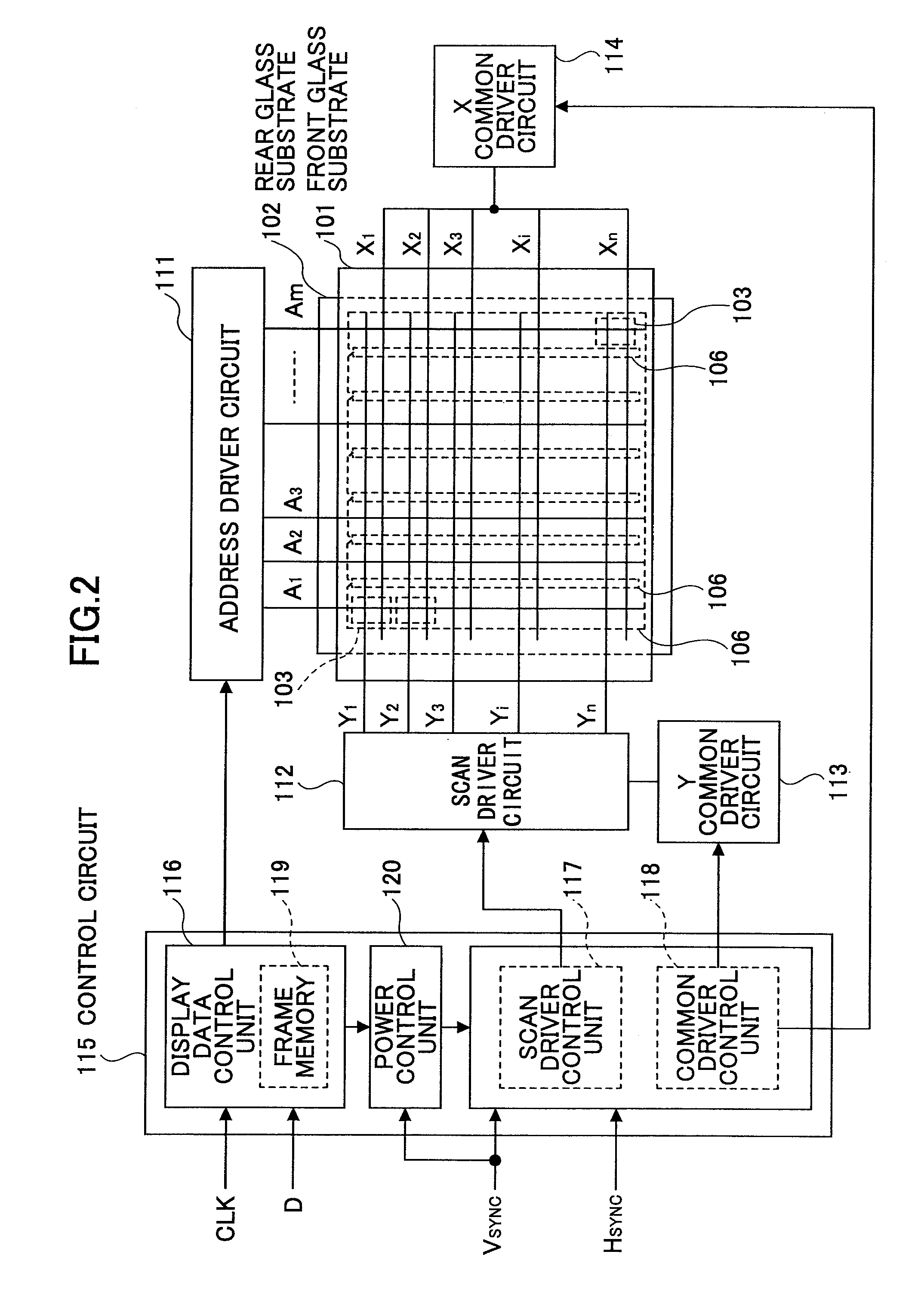
[0061]FIG. 6 is a drawing illustrating an example of the configuration of an embodiment of a plasma display apparatus according to the present invention. In FIG. 6, the same elements as those of FIG. 2 are referred to by the same numerals, and a description thereof will be omitted.

[0062]The plasma display apparatus illustrated in FIG. 6 differs from the plasma display apparatus of FIG. 2 in the functions of a power control unit 200 and a common driver control unit 201. The power control unit 200 of the control circuit 115 calculates the duration of one frame (i.e., one frame length) based on the vertical synchronizing signal, and also calculates the display load ratio based on display data, followed by calculating a pulse count control parameter based on the calculated frame length and the display load ratio. In so doing, the pulse count control parameter is gen...


PUM


Abstract

A plasma display apparatus includes a plasma display panel having a plurality of sustain electrodes and a plurality of scan electrodes, a driver circuit to apply sustain pulses to the plurality of sustain electrodes and the plurality of scan electrodes to generate sustain discharges, and a control circuit to control the driver circuit such that a total light emitting pulse count defined as a total number of sustain pulses in one display frame is set equal to a predetermined pulse count defined as a function of a display load ratio, and such that the total light emitting pulse count is set lower than the predetermined pulse count upon detecting a predetermined condition, wherein the control circuit is configured to cause the driver circuit to selectively generate first sustain pulses with timing for clamping to a predetermined voltage being first timing and second sustain pulses with timing for clamping to the predetermined voltage being second timing, and configured to cause a ratio between a number of the first sustain pulses and a number of the second sustain pulses to be different between a case of the total light emitting pulse count being the predetermined pulse count and a case of the total light emitting pulse count being smaller than the predetermined pulse count.

Description

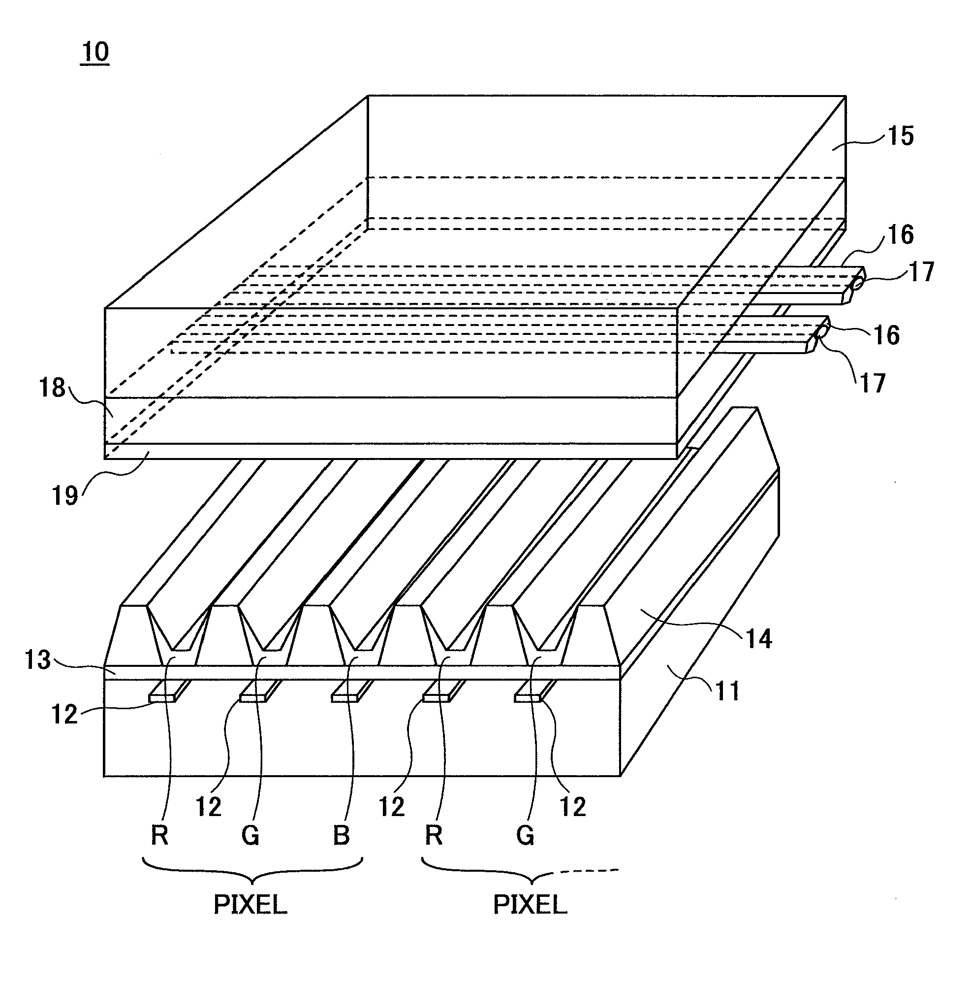
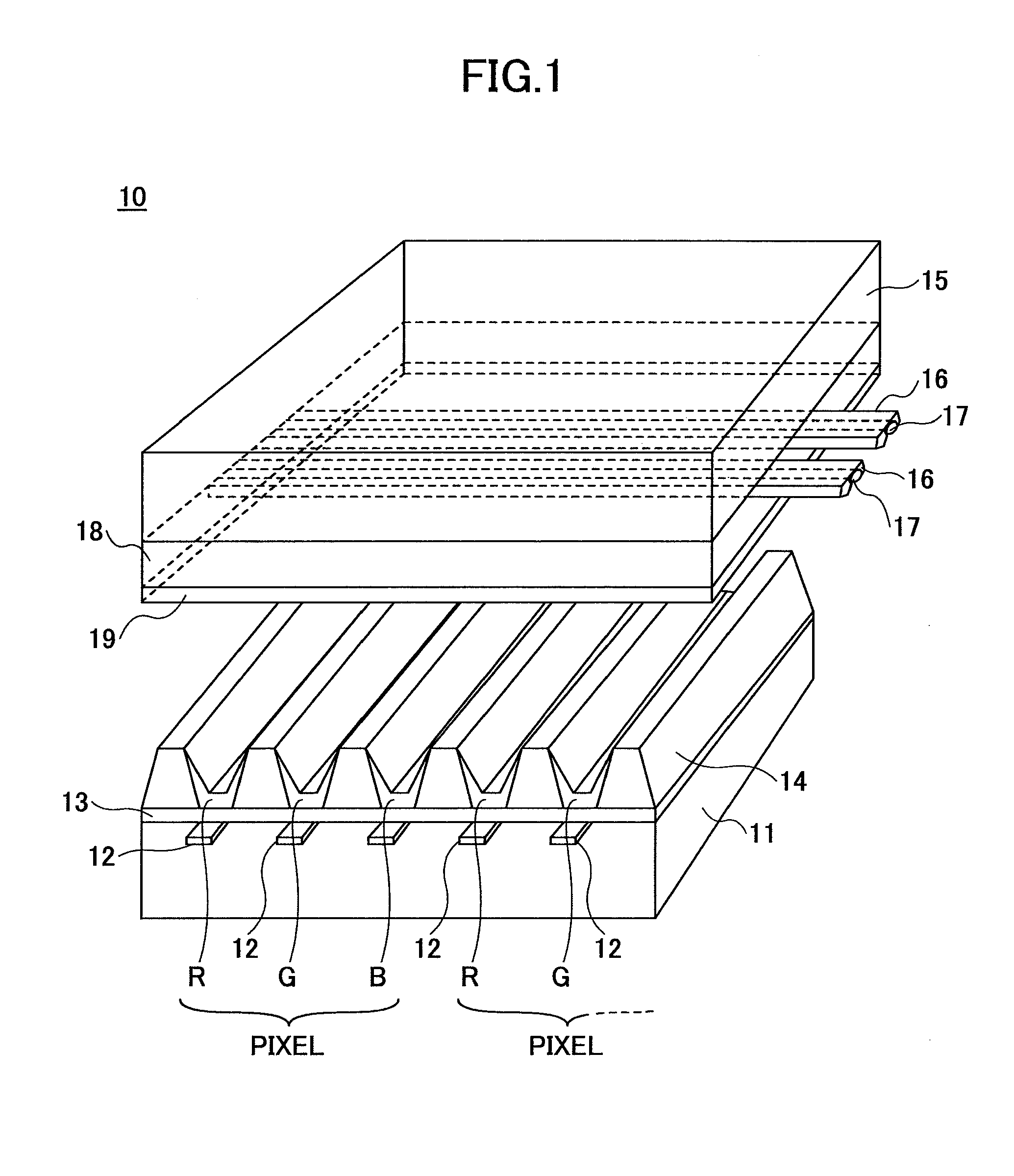
TECHNICAL FIELD[0001]The present invention generally relates to image display apparatuses and methods of driving such apparatuses, and particularly relates to a sub-frame-method-based plasma display apparatus and a method of driving such a plasma display panel.BACKGROUND ART[0002]Flat display apparatuses using flat display panels have been put to practical use in wide areas of application from small displays to large displays, and are replacing conventional cathode-ray tubes. In the field of large-size displays, the plasma display panel (PDP) is regarded as superior due to its advantageous characteristics derived from the principle of operation and configuration, and are commercialized as mainstream products.[0003]FIG. 1 is a cross-sectional view of a three-electrode-type flat-plane-discharge AC-PDP panel serving as an example of a large-size display apparatus.[0004]The three-electrode-type flat-plane-discharge AC-PDP panel includes two glass substrates, i.e., a front glass substrat...

Claims


Application Information

Patent Timeline
IPC IPC(8): G09G3/10G06F3/038G09G3/28G09G3/288G09G3/291G09G3/294G09G3/296G09G3/298
CPCG09G3/2944G09G2360/16G09G2330/021G09G3/2965
Inventor KUMAGAI, JUNICHIITOKAWA, NAOKIITOU, KATSUMIKIMURA, MASAKI
Owner HITACHI LTD
Learn More