
Light shift compensation device of image composition device for multicolor holography

a multi-color holographic and compensation device technology, applied in the field of light shift compensation devices, can solve the problems of difficult to construct a multi-colored three-dimensional image, image cannot be superimposed, original color of objects cannot be faithfully presented,

Inactive Publication Date: 2011-10-27
CHANG JUI TSUNG
View PDF3 Cites 11 Cited by
  • Summary
  • Abstract
  • Description
  • Claims
  • Application Information

AI Technical Summary

Benefits of technology

"The present invention is a light shift compensation device for multicolor holography that allows for the creation of a complete multicolor solid image by superimposing images of different colors. The device includes an illuminant unit, a beamsplitting unit, a compensating unit, a projecting unit, a capturing unit, and a negative. The compensating unit includes a first filter and a fine tuning unit that adjusts the angle of incidence of a reference wave on the negative. The projecting unit includes a second filter, a displaying plate, a recording unit, and a computer that processes the images and integrates them. The fine tuning unit adjusts the angle of the reference wave based on the images in different colors. The device allows for the creation of high-quality multicolor images with accurate color representation."

Problems solved by technology

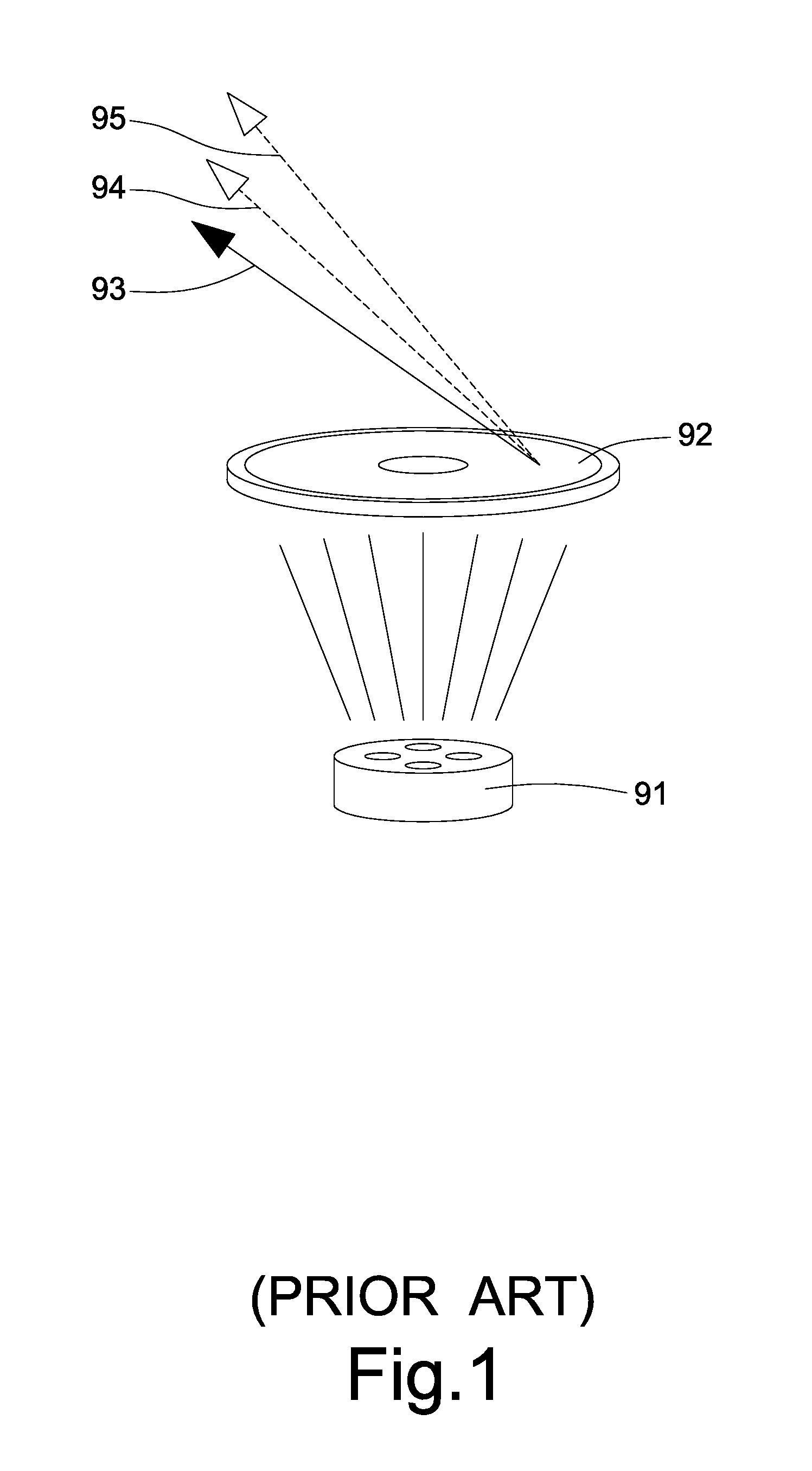
Especially, while reconstructing the red image, the green image, and the blue image under the basic of a white light source, the images are unable to be superimposed since the angles of diffraction and the angles of projection of the images are all diverse.
As a result, it is difficult to construct a multicolored three-D image.
As a result, the reconstructed solid image of such hologram contributes to monochromatic images with three separated colors, and the original color of objects cannot be faithfully presented.

Method used


Image

  • Light shift compensation device of image composition device for multicolor holography
  • Light shift compensation device of image composition device for multicolor holography
  • Light shift compensation device of image composition device for multicolor holography

Examples


Embodiment Construction

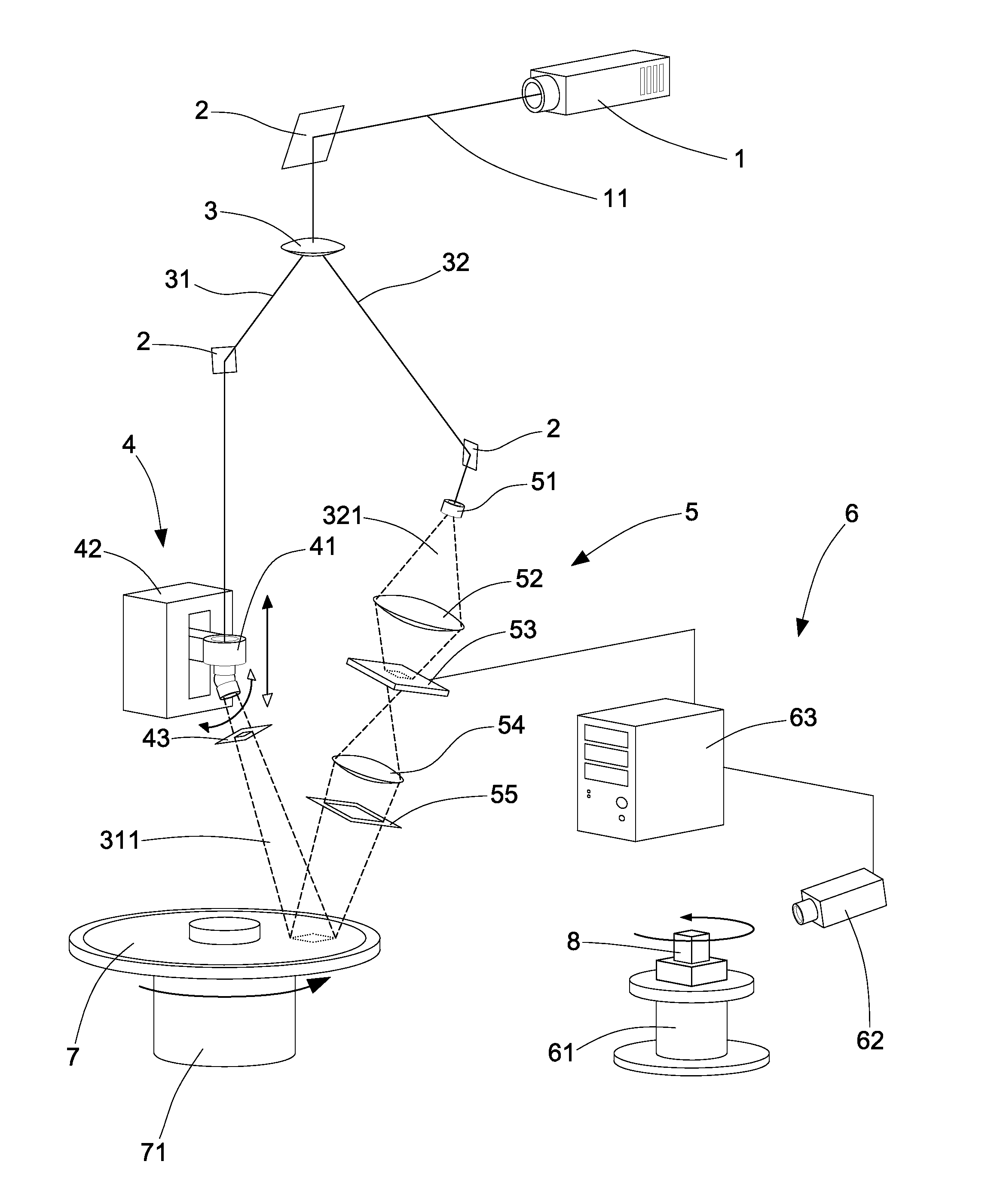
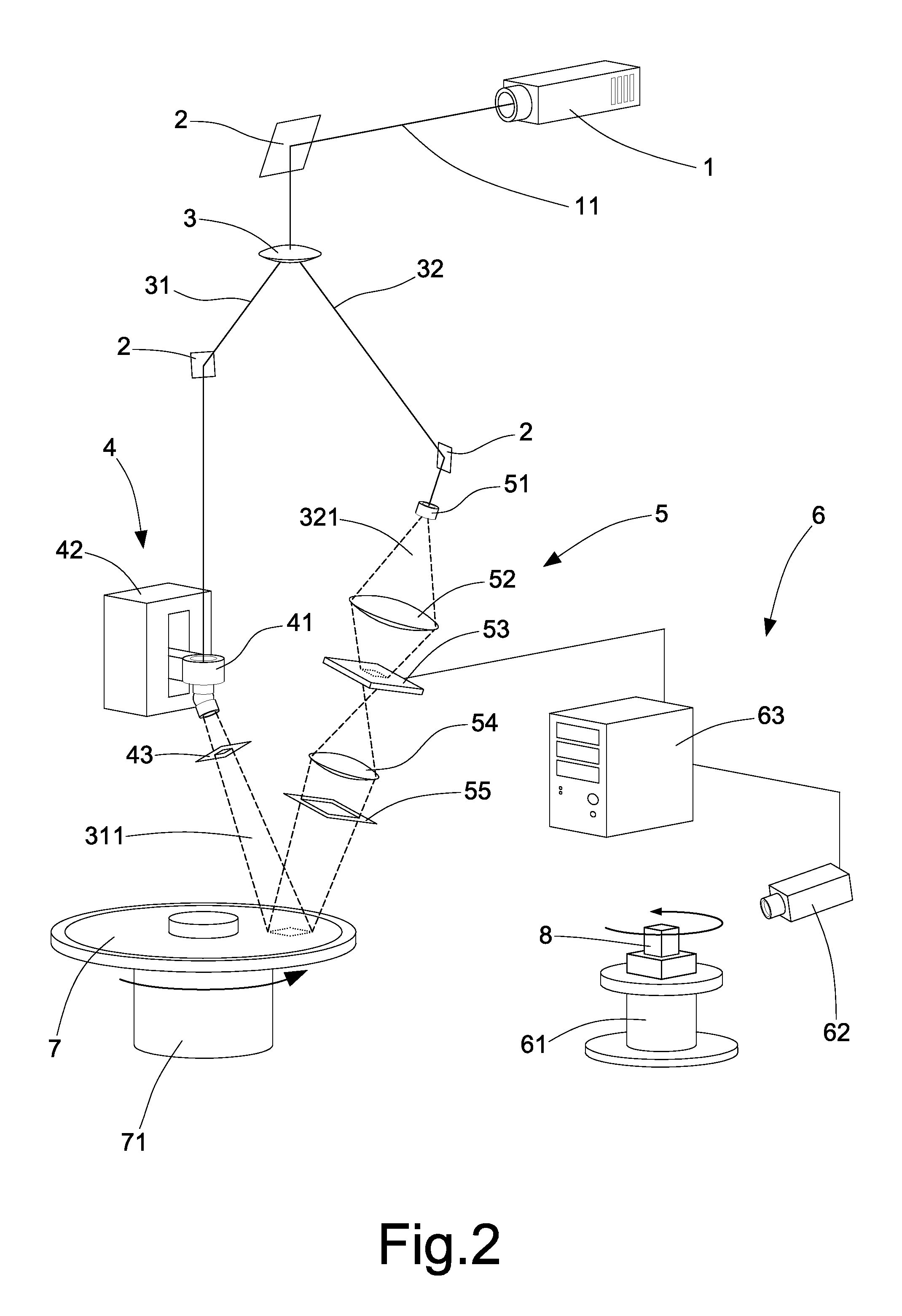
[0035]Referring to FIG. 2, a light shift compensation device of an image composition device for the multicolor holography comprises an illuminant unit 1, a number of plane mirrors 2, a beamsplitting unit 3, a compensating unit 4, a projecting unit 5, a capturing unit 6, and a negative 7.

[0036]The illuminant unit 1 adopts a laser generator that emits laser beams 11 of different wavelengths. According to the scope of the wavelength, the laser beams 11 include the invisible light and the visible light, such as the red beam, the green beam, or the blue beam.

[0037]The plane mirrors 2 without limiting the numbers, adopting the lens that reflects beams with high efficiency, are fittingly installed on the present invention for varying or guiding a traveling route of the laser beam 11.

[0038]The beamsplitting unit 3 splits the laser beam 11 into two coherent beams. Namely, by penetrating the beamsplitting unit 3, the beam 11 is split into a reference beam 31 and an object beam 32. Wherein, th...


PUM


Abstract

A light shift compensation device of an image composition device for the multicolor holography utilizes a light source provider to emit a beam split into an object beam and a reference beam via a beamsplitting unit. The object beam, shined on a projecting unit, is transformed into an object wave for projecting two-D images of the object on a negative. The reference beam is transformed into a reference wave by a compensating unit to adjust the irradiation angle and thence project on the negative. Interference fringes formed by the object wave and the reference wave projecting on the negative record two-D images of the object on the negative. The two-D images projected by the object wave are separated into the red image, the green image, and the blue image, which are directed to the three fundamental colors. The image of one single color is adopted for being recorded on the negative each time. The images of the three fundamental colors are successively processed by three times of double-exposure on the negative to compose a true color image. The angle of projection of the reference wave is adjusted by the compensating unit, so that the angles of diffraction of the green image and the blue image recorded on the negative are changed.

Description

BACKGROUND OF THE INVENTION[0001]1. Field of the Invention[0002]The present invention relates to a light shift compensation device, especially to a light shift compensation device of an image composition device for the multicolor holography that utilizes interference fringes generated by a reference wave and an object wave to record images on a negative. Thereby, the negative reconstructs a recording device for a solid image, and the reference wave adjusts an angle of irradiation via a compensating unit to previously amend angles of deviation of the diffracted three fundamental colors.[0003]2. Description of the Related Art[0004]The conventional device for constructing a hologram substantially separates a light source into a reference beam and an object beam. Wherein, filtered into an object wave, the object beam projects a two-D image of an object on the hologram. The reference beam filtered into a reference wave, the reference wave is projected on the hologram with an angle of inc...

Claims


Application Information

Patent Timeline
Patent Type & Authority Applications(United States)
IPC IPC(8): H04N5/89G03B35/16
CPCG03B35/16G03H2210/30G03H1/0486G03H1/265G03H1/30G03H2001/0413G03H2001/0473G03H2001/2271G03H2001/303G03H2210/13G03H2210/22G03H2210/42G03H2210/454G03H2222/18G03H2222/36G03H2270/22G03H1/2249G03H1/0406
Inventor CHANG, JUI-TSUNG
Owner CHANG JUI TSUNG
Learn More