Rotation detecting apparatus and rotation detecting system

a technology of rotating detection and rotating equipment, which is applied in the direction of dynamo-electric converter control, dc motor rotation control, instruments, etc., can solve the problems of increasing the weight of the vehicle, increasing the cost of manufacture, and increasing the probability of erroneous detection

Inactive Publication Date: 2011-10-27
NIPPON SOKEN +1
View PDF3 Cites 28 Cited by
  • Summary
  • Abstract
  • Description
  • Claims
  • Application Information

AI Technical Summary

Problems solved by technology

However, in the above method of detecting the rotational state by using the sensor, a sensor-mount space is required for each direct-current motor.
As a result, the above requirement increases the weight of the vehicle and increases a cost of manufacture.
However, in the above method, the erroneous detection may be more likely to occur when the rotational speed is further reduced because the surge pulse becomes more difficult to detect when the rotational speed is reduced substantially.
For example, when the direct current changes with other factors other than the connection to the resistor, such as the change of the power source voltage, the rotation pulse may be erroneously detected disadvantageously.

Method used


Image

  • Rotation detecting apparatus and rotation detecting system
  • Rotation detecting apparatus and rotation detecting system
  • Rotation detecting apparatus and rotation detecting system

Examples


first embodiment

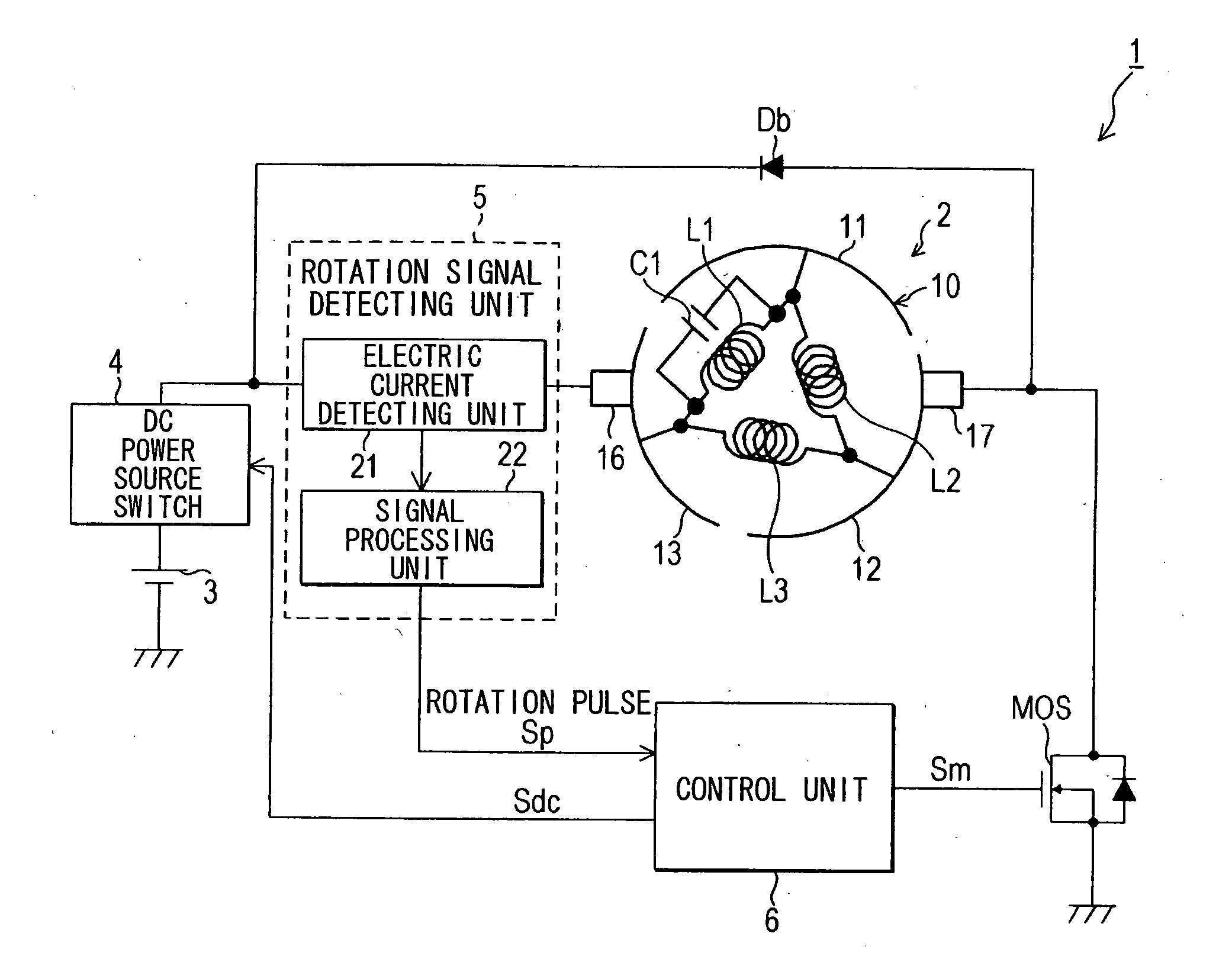
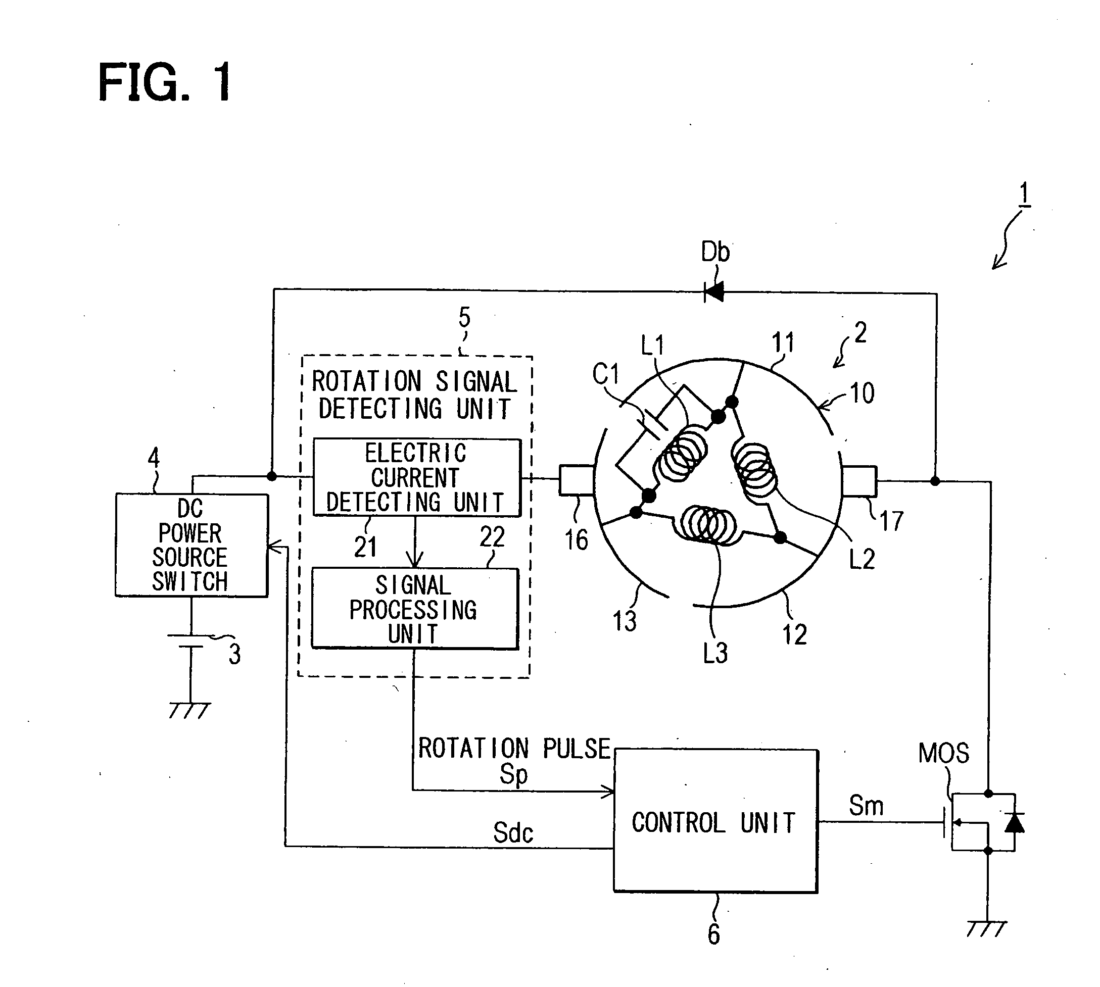
[0041]FIG. 1 shows a schematic configuration of a rotation detecting system that employs an embodiment of the present invention. As shown in FIG. 1, a rotation detecting system 1 of the present embodiment includes a direct-current motor (hereinafter referred to as merely a “motor”) 2, and is configured to detect a rotation angle of the motor 2. The rotation detecting system 1 further includes a direct-current power source 3, a direct-current power source switch 4, a rotation signal detecting unit 5, and a control unit 6. The direct-current power source 3 outputs direct-current voltage for rotating the motor 2 or for generating torque. The direct-current power source switch 4 opens and closes a supply route (energization route) of direct-current electric power from the direct-current power source 3 to the motor 2. In other words, the direct-current power source switch 4 allows and prohibits flow of the direct-current electric power through the supply route from the direct-current pow...

second embodiment

[0133]FIG. 7 shows a schematic configuration of a rotation detecting system 30 according to the second embodiment. The rotation detecting system 30 of the present embodiment is configured to detect the rotation angle and the rotational speed of a target motor 31 similarly to the first embodiment. Furthermore, the rotation detecting system 30 is configure to detect a rotational direction of the motor 31.

[0134]The rotation detecting system 30 of the present embodiment includes the direct-current power source 3 and the electric current detecting unit 21. The direct-current power source 3 applies direct-current voltage to the motor 31 for driving the motor 31, and the electric current detecting unit 21 is provided between the direct-current power source switch 4 and the motor 31. Also, similar to the rotation detecting system 1 of the first embodiment, the drive switch MOS is provided in the route between the motor 31 and the ground, and the drive switch MOS is PWM-controlled by a contr...

third embodiment

[0160]FIG. 11 shows a schematic configuration of a rotation detecting system 40 of the third embodiment. The rotation detecting system 40 of the present embodiment is also configured to detect the rotation angle of the motor 2 similar to the rotation detecting system 1 of the first embodiment shown in FIG. 1. The rotation detecting system 40 includes the direct-current power source 3, the rotation signal detecting unit 5, and the direct-current power source switch 4 similarly to the first embodiment. As above, the direct-current power source 3 applies the direct-current voltage to the motor 2 in order to drive the motor 2. The rotation signal detecting unit 5 generates the rotation pulse Sp based on the electric current supplied to the motor 2.

[0161]Thus, components of the present embodiment similar to those in the first embodiment are indicated by the same numerals used in the first embodiment, and the explanation thereof will be omitted. Thus, the configuration of the present embo...


PUM


Abstract

A rotation detecting apparatus for detecting a rotational state of a direct-current motor includes a driving device, a control device, an energization detecting device, an alternating-current component detecting device, and a rotational state detecting device. An impedance between brushes of the motor changes periodically in accordance with rotation of the motor. The alternating-current component detecting device detects change of an alternating-current component of electric current that is supplied to the motor based on an electrical quantity. The change of the alternating-current component is caused by change of the impedance caused in accordance with the rotation. The rotational state detecting device detects at least one of a rotation angle, a rotational direction, and a rotational speed of the motor based on a detection result of the alternating-current component detecting device.

Description

CROSS REFERENCE TO RELATED APPLICATION[0001]This application is based on and incorporates herein by reference Japanese Patent Application No. 2010-42599 filed on Feb. 26, 2010.BACKGROUND OF THE INVENTION[0002]1. Field of the Invention[0003]The present invention relates to a rotation detecting, apparatus that detects a rotational state of a direct-current motor, such as a rotation angle or a rotational direction, and relates to a rotation detecting system having the rotation detecting apparatus.[0004]2. Description of Related Art[0005]A direct-current brush motor (hereinafter referred to as a “direct-current motor”) has been conventionally employed in a vehicle. For example, the direct-current motor adjusts opening / closing angles of an air mix damper for adjusting temperature and of a mode damper for switching air outlets of an air conditioner of the vehicle. In the control of the above direct-current motor, a rotational state of the direct-current motor, such as a rotation angle, a ...

Claims


Application Information

Patent Timeline
Patent Type & Authority Applications(United States)
IPC IPC(8): H02P7/29H02P3/08H02P5/50G01D5/245G01P3/481H02P7/03
CPCG01P3/48H02P7/0094H02K11/001H02K11/20
Inventor TANAKA, KENFUKAGAWA, YASUHIROTOUGE, MASARU
Owner NIPPON SOKEN
Why Eureka
Try Eureka