Method for Assembling Tendons

a technology of tendons and tendons, which is applied in the field of assembling tendons, can solve the problems of increasing the cost of couplings, requiring more time and more joints, and no other floating production facility design offers optimal motion stability characteristics, etc., and achieves the effect of low cost facilities

Active Publication Date: 2011-10-27
SINGLE BUOY MOORINGS INC
View PDF5 Cites 4 Cited by
  • Summary
  • Abstract
  • Description
  • Claims
  • Application Information

AI Technical Summary

Benefits of technology

The present invention is a new method of assembling tendons offshor

Problems solved by technology

No other floating production facility design offers the optimal motion and stability characteristics of a tension leg platform.
Smaller facilities can be

Method used


Image

  • Method for Assembling Tendons
  • Method for Assembling Tendons

Examples


Embodiment Construction

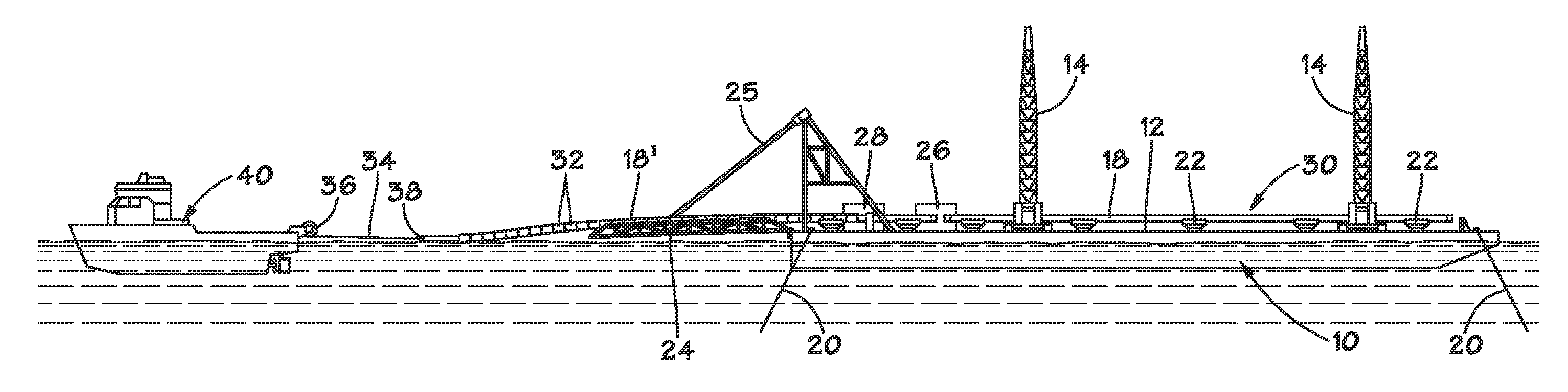
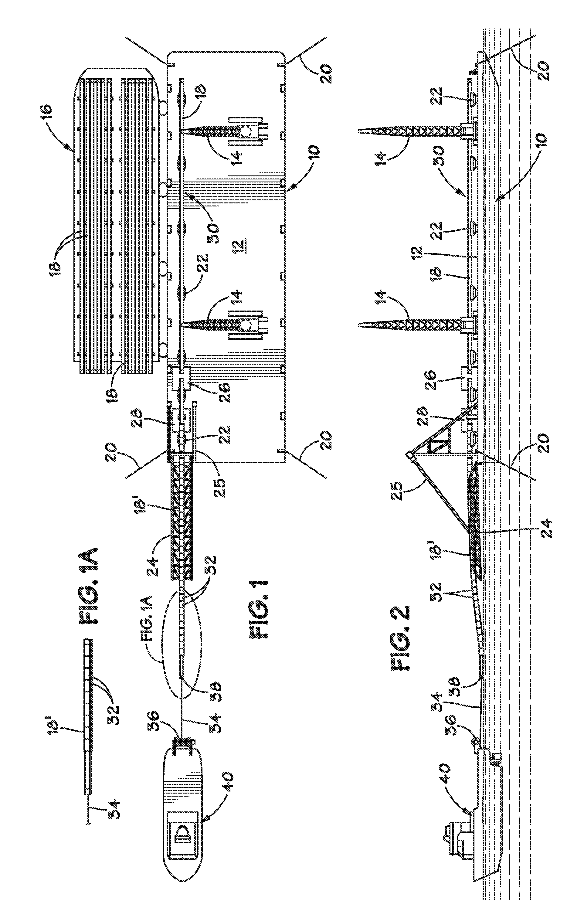
The costs of fabricating a tendon system and the installation of a tendon system are both related to the length of the individual pipe joints and the cost of the offshore support vessels needed to handle them.

The one piece we tow system requires a large on-shore facility to handle the long tendons as they are assembled, but requires a minimum offshore spread to up-end the tendons.

There are also the costs associated with the risk of a long tow (in both known examples of this type of installation, one or more tendons have been dropped during the tow). This configuration does not require any couplings, which can result in large cost savings.

Vertical stalking requires a vessel with the ability to handle joints of finished tendon pipe and a tower to hold the joint correctly aligned while the connection is made. For typical tendon joint lengths of 250 to 300 ft., a large offshore crane vessel is used which is a very expensive offshore spread.

Reducing the length of joints to 120 to 150 ft....


PUM


Abstract

A tendon is assembled in a horizontal orientation using connectors or by welding at a weld station on a barge or other vessel located at or near the installation site of a tension leg platform. During assembly, the tendon is pulled away from the assembly vessel and tensioned by a tug or offshore work vessel. When fully assembled, the tendon may be up-ended in a manner similar to a wet-towed tendon, and then either pre-installed using floats or passed over to a TLP which is on-site and ready to receive tendons.

Description

STATEMENT REGARDING FEDERALLY SPONSORED RESEARCH OR DEVELOPMENTNot ApplicableBACKGROUND OF THE INVENTION1. Field of the InventionThis invention relates to offshore platforms. More particularly, it relates to a method for assembling the tendons used to moor a tension leg platform.2. Description of the Related Art including information disclosed under 37 CFR 1.97 and 1.98A tension leg platform (TLP) is ideal for developing deepwater reserves. No other floating production facility design offers the optimal motion and stability characteristics of a tension leg platform. The TLP is vertically moored using tubular steel tendons and is supported by a buoyant hull. The tendon stiffness results in a system with virtually no heave, roll or pitch. This makes the TLP suitable for both dry tree and sub-sea completions.A number of TLP solutions for deepwater field development have been designed, built and deployed around the world. The designs include both mono-column TLPs and mufti-column TLPs.T...

Claims


Application Information

Patent Timeline
IPC IPC(8): E02B17/00B63B38/00B63B35/44
CPCB63B21/502E02B17/02E02B17/00
Inventor LEVERETTE, STEVEN JOHN
Owner SINGLE BUOY MOORINGS INC
Why Eureka
Try Eureka