Systems and Methods for Forming Metal Matrix Composites

a metal matrix composite and composite technology, applied in the field of metal matrix composites, can solve the problems of high thermal strain and the inability of most fibers to survive, and achieve the effect of reducing the disadvantages and eliminating the problems of forming metal matrix composites

Inactive Publication Date: 2017-12-21
LOCKHEED MARTIN CORP
View PDF4 Cites 1 Cited by
  • Summary
  • Abstract
  • Description
  • Claims
  • Application Information

AI Technical Summary

Benefits of technology

[0003]In accordance with the present disclosure, disadvantages and problems associated with forming metal matrix composites may be reduced or eliminated.
[0007]Technical advantages of embodiments of the disclosure may include electroplating nonconductive fibers at or within a few degrees of room temperature, which creates a metal matrix composite with virtually no internal stresses and no heat-induced damage or interactions with the fibers. Further, the electroplating process requires no touch labor and relatively low cost facilities, which keeps the processing costs low.
[0008]Another advantage of disclosed embodiments of forming metal matrix composites is that they may have a lower coefficient of thermal expansion and a lower density than most conventional metals. Further, disclosed embodiments of metal matrix composites may have improved high temperature properties and damping properties than most conventional metals. For example, a much higher temperature may be possible with disclosed metal matrix composites than with polymer matrix composites. As another technical advantage, in certain embodiments, fugitive forms may be placed in the nonconductive fibers and removed after electroplating to create one or more voids, wherein the voids may be used to construct cooling passages or integral stiffening of the metal matrix composite part. As still another advantage, stiffened metal matrix composite panels may be formed using the electroplating method. Also, the electroplating method may be used to form radii in metal matrix composite parts. In some embodiments, an advantage of forming metal matrix composites using the disclosed electroplating process is that the metal matrix composite may be formed to any desired shape. For example, a metal matrix composite may be formed in the shape of a turbine blade, a rocket engine, a piston, or an air frame part.
[0009]A further advantage of some embodiments of forming metal matrix composites with nonconductive fibers is that aerospace parts may be formed that increase performance of the aircraft. For example, embedding fibers (e.g., ceramic fibers) into metal as discussed herein may allow the metal part (e.g., an engine) to operate at higher temperatures than it could without the fibers. The ability of the metal matrix composite to operate at higher temperatures may enable the aircraft to operate at a higher speed without failing in comparison to a part without fibers. For example, an aluminum part without fibers may operate at 350 degrees Fahrenheit, whereas an aluminum metal matrix composite part with fibers, according to certain embodiments, may operate at 700 degrees Fahrenheit. To achieve the 700 degree Fahrenheit temperature without fibers, a titanium or steel part may be required in place of aluminum. Additionally, the metal matrix composite's ability to operate at higher temperatures may enable an aircraft to operate at the same speed but at a lower weight, which may increase the aircraft's performance.
[0010]Another advantage of fiber reinforcement in a metal matrix is the reduction of the large property differential found in organic and ceramic matrix advanced composites between the in-plane and out-of-plane directions. The metallic matrix has a substantial percentage of the composite in-plane properties, greatly reducing the risk of out-of-plane failures in complex parts and loading scenarios.
[0011]In some embodiments, conductive fibers may be used with a nonconductive coating, which promotes adhesion, producibility, or other properties of the fiber. In certain embodiments, a conductive fiber may be used with electroplating, or any fiber may be used with an electroless plating process, but the preferred process is a nonconductive fiber with an electroplating process.

Problems solved by technology

Most fibers cannot survive this environment, and many fibers will react to the matrix and form undesirable compounds.
Further, cooling the fibers to room temperature can induce thermal strains high enough to destroy the metal matrix composite.

Method used


Image

  • Systems and Methods for Forming Metal Matrix Composites
  • Systems and Methods for Forming Metal Matrix Composites
  • Systems and Methods for Forming Metal Matrix Composites

Examples


Embodiment Construction

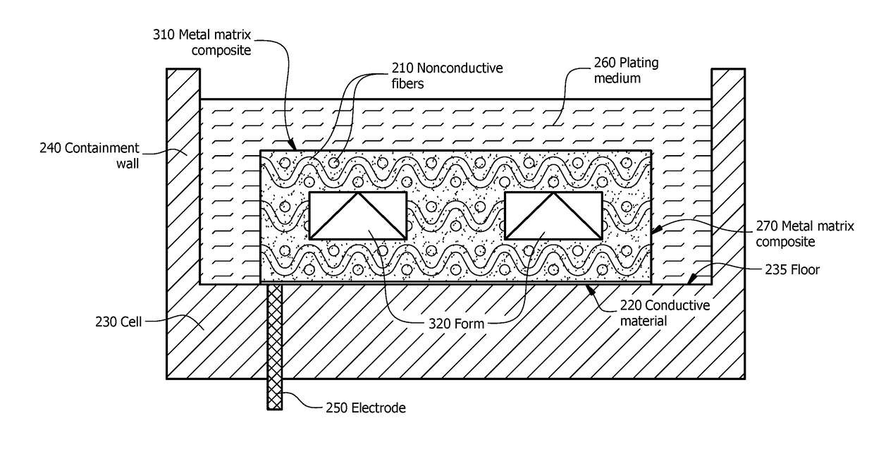
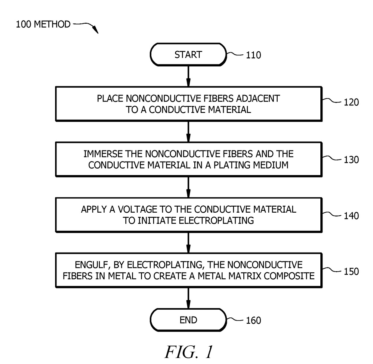
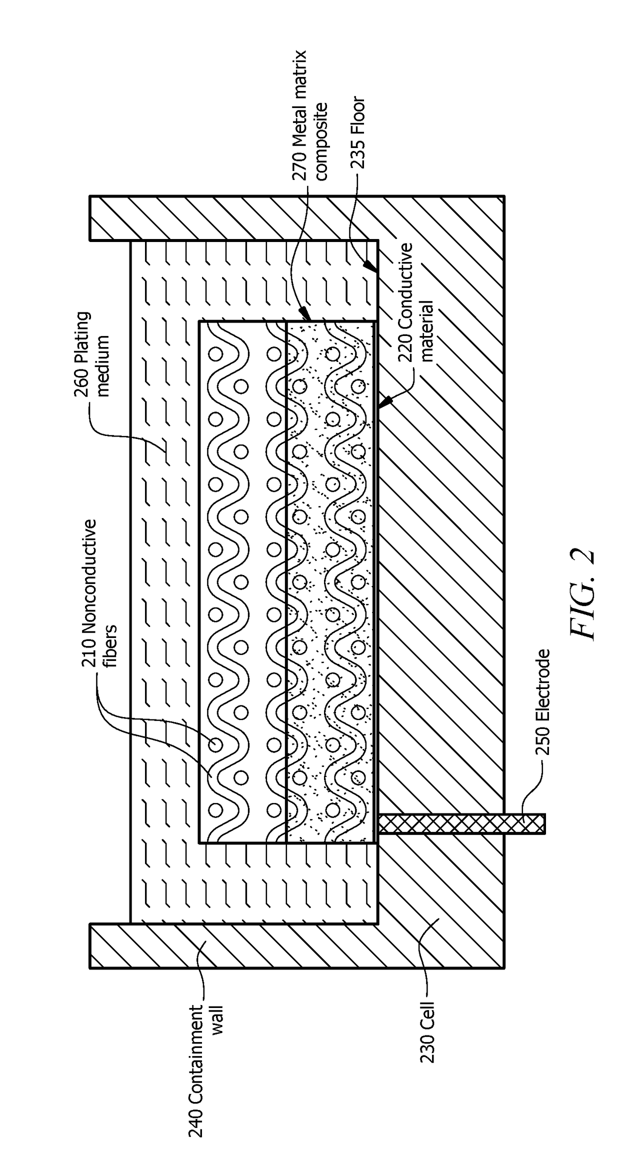
[0020]To facilitate a better understanding of the present disclosure, the following examples of certain embodiments are given. The following examples are not to be read to limit or define the scope of the disclosure. Embodiments of the present disclosure and its advantages are best understood by referring to FIGS. 1 through 6, where like numbers are used to indicate like and corresponding parts.

[0021]Metal matrix composites exhibit superior characteristics over their polymer or ceramic competitors, such as conductivity, strength, ductility, and fracture toughness. However, processing metal matrix composites presents disadvantages. Current processing methods include melting the metal and infusing the metal into fibers or mixing the fibers with a metal powder and sintering to form a solid composite.

[0022]Melting the metal and infusing the metal into fibers exposes the fibers to a reactive metal at 1200 degrees Fahrenheit to 3000 degrees Fahrenheit. Most fibers cannot survive this envi...


PUM


Abstract

In certain embodiments, a method comprises placing nonconductive fibers adjacent to a conductive material, immersing the nonconductive fibers and the conductive material in a plating medium, and applying a voltage to the conductive material to initiate electroplating. The method further comprises engulfing, by electroplating, the nonconductive fibers in metal to create a metal matrix composite.

Description

TECHNICAL FIELD[0001]The present disclosure relates in general to forming composites, and more specifically to systems and methods for forming metal matrix composites.BACKGROUND[0002]Traditional methods of forming metal matrix composites involve melting the matrix, which exposes the fibers to a reactive metal at 1200 degrees Fahrenheit to 3000 degrees Fahrenheit. Most fibers cannot survive this environment, and many fibers will react to the matrix and form undesirable compounds. Further, cooling the fibers to room temperature can induce thermal strains high enough to destroy the metal matrix composite.SUMMARY OF THE DISCLOSURE[0003]In accordance with the present disclosure, disadvantages and problems associated with forming metal matrix composites may be reduced or eliminated.[0004]In one embodiment, a method includes placing nonconductive fibers adjacent to a conductive material, immersing the nonconductive fibers and the conductive material in a plating medium, applying a voltage ...

Claims


Application Information

Patent Timeline
Patent Type & Authority Applications(United States)
IPC IPC(8): C25D1/00C25D1/08C25D1/20B33Y10/00B33Y70/00B33Y80/00
CPCC25D1/003C25D1/20B33Y80/00B33Y10/00B33Y70/00C25D1/08C25D1/00C25D5/022C25D7/04C25D15/00
Inventor THOMAS, JR., WILLIAM ALFRED
Owner LOCKHEED MARTIN CORP
Why Eureka
Try Eureka