Storage Battery System

Active Publication Date: 2011-10-27
HITACHI VEHICLE ENERGY
View PDF6 Cites 12 Cited by
  • Summary
  • Abstract
  • Description
  • Claims
  • Application Information

AI Technical Summary

Benefits of technology

[0014]According to the 7th aspect of the present invention, the judgment unit of a storage battery system according to the 6th aspect may increase the cooling performance of the cooling system when a fail

Problems solved by technology

However, with the conventional storage battery system described above, since a battery temperature is estimated based on an amount of heat generation due to a charge and discharge current of a secondary battery, ambient temperature, an o

Method used


Image

  • Storage Battery System
  • Storage Battery System
  • Storage Battery System

Examples


Example

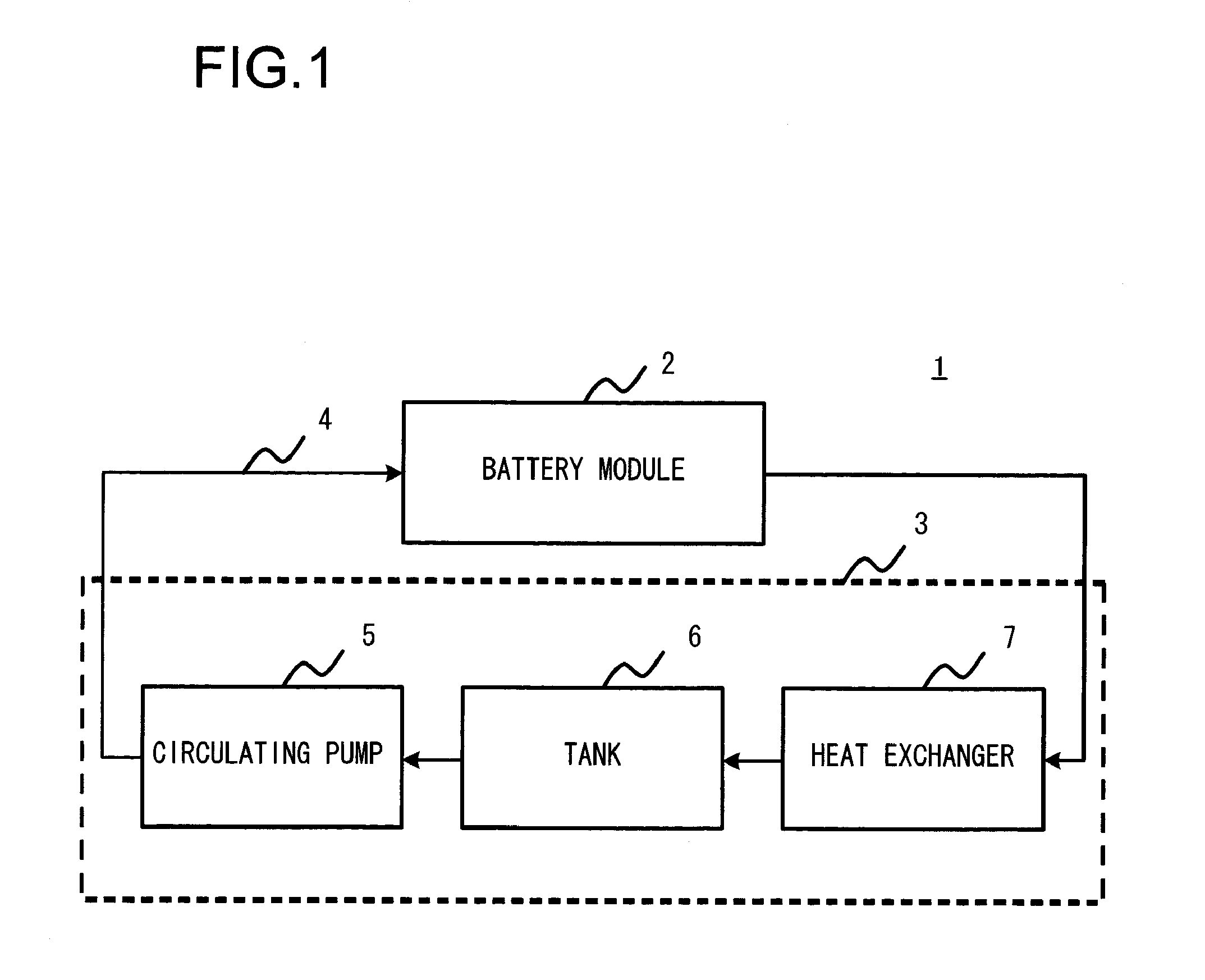
[0028]FIG. 1 illustrates a configuration of a liquid-cooled storage battery system according to an embodiment. A storage battery system 1 according to the embodiment comprises a battery module 2, a cooling system 3, a cooling medium 4, and the like. The cooling system 3 circulates the cooling medium 4 to the battery module 2. The cooling medium 4 absorbs heat generated by the battery module 2 and transfers the heat to the outside of the battery module 2. For example, water, an antifreeze liquid, or the like can be used as the cooling medium 4. The liquid-cooling type cooling system 3 comprises a circulating pump 5, a tank 6, a heat exchanger 7, and the like. The circulating pump 5 supplies kinetic energy to the cooling medium 4 for sending the cooling medium 4 to the battery module 2. The tank 6 stores the cooling medium 4 to be circulated and supplies the cooling medium 4 to the circulating pump 5. The heat exchanger 7 cools the cooling medium 4 that has been reclaimed after absorb...


PUM


Abstract

A storage battery system includes: a secondary battery; a holding member comprising a flow channel of a cooling medium for cooling the secondary battery, which holds the secondary battery; a medium temperature measuring unit that measures temperatures T1 and T2 of the cooling medium at two locations in the flow channel; a battery temperature measuring unit that measures a temperature T3 of the secondary battery; and a judging unit that repetitively calculates a coefficient α and that judges a cooling performance of the secondary battery based on a variation of the coefficient α, the coefficient α being defined as (T3−T1)/(T2−T1), (T3−T2)/(T2−T1), or (T3−T2)/(T3−T1).

Description

INCORPORATION BY REFERENCE[0001]The disclosure of the following priority application is herein incorporated by reference:[0002]Japanese Patent Application No. 2010-102610 filed Apr. 27, 2010.BACKGROUND OF THE INVENTION[0003]1. Field of the Invention[0004]The present invention relates to a storage battery system using a secondary battery.[0005]2. Description of Related Art[0006]Performance and life time of a secondary battery strongly depend on the temperature of the secondary battery. Since the likelihood of deterioration increases at high temperatures, with a secondary battery system that requires a large current such as that of a hybrid vehicle, a cooling performance of a cooling system during charge and discharge must be accurately monitored. Cooling methods of secondary batteries can be divided into two methods, namely, an air-cooling method in which air is supplied by a fan to cool a secondary battery and a liquid-cooling method in which a liquid cooling medium is circulated to...

Claims


Application Information

Patent Timeline
IPC IPC(8): H01M10/50H01M10/48H01M10/60H01M10/613H01M10/625H01M10/633H01M10/655H01M10/6561H01M10/6567
CPCH01M10/486H01M10/5004H01M10/5067H01M10/5022H01M10/5048H01M10/5077H01M10/633H01M10/6563H01M10/6568H01M10/613H01M10/6554Y02E60/10
Inventor SUGA, ATSUO
Owner HITACHI VEHICLE ENERGY
Why Eureka
Try Eureka