Vehicle air conditioner with vapor-compression refrigerant cycle and method of operating the same

Inactive Publication Date: 2006-06-20
DENSO CORP
View PDF8 Cites 13 Cited by
  • Summary
  • Abstract
  • Description
  • Claims
  • Application Information

AI Technical Summary

Benefits of technology

[0007]Further, it is another object of the present invention to provide a method of operating a new air-conditioner having sufficient cooling performance.
[0014]The above method of operating the air-conditioner provides sufficient cooling performance. Moreover, the increase of the cooling performance performs to eliminate the fog of the windshield immediately, and performs to obtain a required cooling performance immediately.

Problems solved by technology

When the opening degree of the throttle is fixed, the pumping performance of the ejector is limited.
In some cases, the ejector may not send the refrigerant to the evaporator sufficiently, so that the cooling performance of the air-conditioner becomes short.
Moreover, when the cooling performance of the air-conditioner reduces, a dehumidifying performance of the air-conditioner also reduces, so that a windshield of the vehicle may be fogged.

Method used


Image

  • Vehicle air conditioner with vapor-compression refrigerant cycle and method of operating the same
  • Vehicle air conditioner with vapor-compression refrigerant cycle and method of operating the same
  • Vehicle air conditioner with vapor-compression refrigerant cycle and method of operating the same

Examples


first embodiment

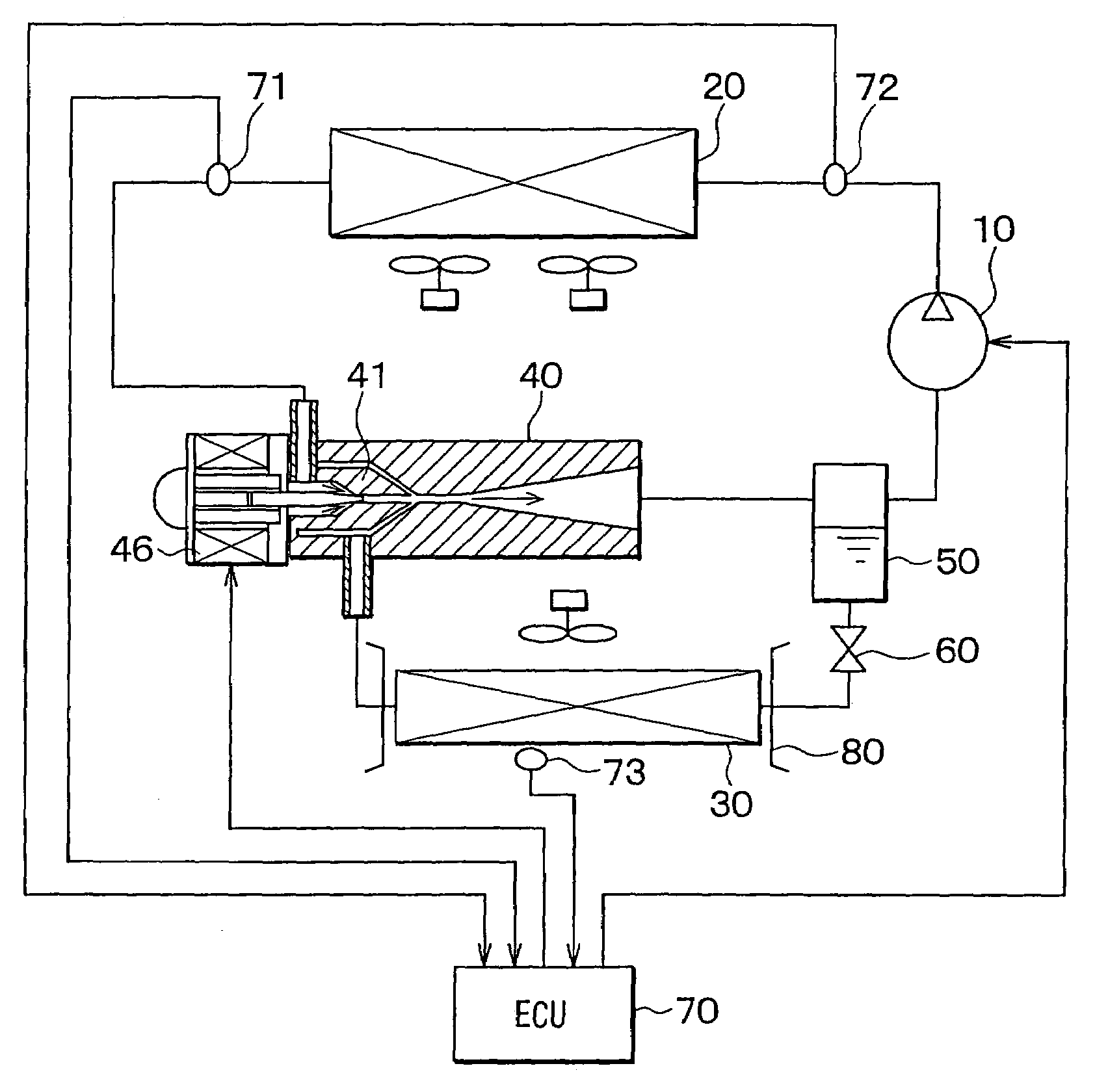
[0024]An air-conditioner with a vapor compression refrigerant cycle according to a first embodiment of the present invention is shown in FIG. 1. The air-conditioner includes an ejector 40, so that the vapor compression refrigerant cycle provides an ejector cycle.

[0025]The air-conditioner with the ejector cycle includes a compressor 10, a radiator 20, an evaporator 30, the ejector 40, a separator 50, a throttle 60, an electronic control unit (i.e., ECU) 70, a temperature sensor 71, a pressure sensor 72, and an evaporation sensor 73. The compressor 10 is a variable displacement compressor operated by a driving force from a driving engine, and is used as a pumping means for sucking and compressing refrigerant. The radiator 20 as a high-pressure side heat exchanger exchanges heat between the refrigerant discharged from the compressor 10 and the outside air outside a passenger compartment of a vehicle so that the radiator 20 cools the refrigerant.

[0026]In this embodiment, the refrigerant...

second embodiment

[0045]When the windshield of the vehicle is fogged in accordance with the change of the driving environment, when the passenger selects the defog mode, which provides to blow the air-conditioning air toward the windshield, or when the detected temperature of the evaporation sensor 73 becomes large so that the cooling performance of the evaporator 30 is reduced, the displacement of the compressor 10 is increased so that the amount of the refrigerant discharged from the compressor 10 per unit of time is increased. Then, the opening degree of the throttle of the nozzle 41 is increased.

third embodiment

[0046]When the windshield of the vehicle is fogged in accordance with the change of the driving environment, when the passenger selects the defog mode, which provides to blow the air-conditioning air toward the windshield, or when the detected temperature of the evaporation sensor 73 is increased so that the cooling performance of the evaporator 30 is reduced, the opening degree of the throttle of the nozzle 41 is increased, and simultaneously the displacement of the compressor 10 is increased so that the amount of the refrigerant discharged from the compressor 10 per unit of time is increased.


PUM


Abstract

An air-conditioner includes a compressor, a radiator, an evaporator, an ejector, and a separator. The compressor compresses refrigerant and variably controls an amount of the refrigerant. The radiator cools high-pressure refrigerant. The evaporator cools air blowing into a passenger compartment of a vehicle. The ejector having a nozzle jets the refrigerant at high speed. The separator separates the refrigerant into gas refrigerant and liquid refrigerant. An opening degree of a throttle of the nozzle in the ejector becomes larger so as to increase a cooling performance of the air-conditioner when the amount of the refrigerant discharged from the compressor is smaller than a maximum amount of the refrigerant.

Description

CROSS REFERENCE TO RELATED APPLICATION[0001]This application is based on Japanese Patent Application No. 2002-262964 filed on Sep. 9, 2002, the disclosure of which is incorporated herein by reference.FIELD OF THE INVENTION[0002]The present invention relates to an air conditioner with a vapor-compression refrigerant cycle. Specifically, the present invention relates to an ejector cycle of the vapor-compression refrigerant cycle, which provides to transfer heat of a low-temperature side to a high-temperature side. The air conditioner is suitably used for a vehicle.BACKGROUND OF THE INVENTION[0003]An ejector cycle of a vapor-compression refrigerant cycle in an air-conditioner for a vehicle is performed by an ejector. In the ejector cycle, the ejector decompresses and expands high-pressure refrigerant so that suction pressure of a compressor is increased in accordance with converting expansion energy to pressure energy and that refrigerant of a low-pressure side circulates by a pumping ...

Claims


Application Information

Patent Timeline
IPC IPC(8): F25B19/02F25B1/06F25B1/00B60H1/32F25B9/00F25B41/00
CPCB60H1/3204F25B9/008F25B41/00B60H1/3217F25B2700/21173B60H2001/3245B60H2001/3251B60H2001/326B60H2001/3261B60H2001/3297B60H2001/3298F25B2309/061F25B2341/0012F25B2341/0013F25B2600/17F25B2700/02F25B2700/1931F25B2700/2102F25B2700/21172F25B2400/23
Inventor NISHIDA, SHINTOMATSU, YOSHITAKA
Owner DENSO CORP
Why Eureka
Try Eureka