
Transcatheter Prosthetic Heart Valve Delivery Device With Passive Trigger Release

a prosthetic heart valve and transcatheter technology, applied in the field of systems, devices, and methods for percutaneous implantation of prosthetic heart valves, can solve the problems of significant patient trauma and discomfort, mixed results, and inability to achieve the effect of minimizing possible malfunctions of the release assembly

Active Publication Date: 2011-10-27
MEDTRONIC INC
View PDF4 Cites 167 Cited by
  • Summary
  • Abstract
  • Description
  • Claims
  • Application Information

AI Technical Summary

Benefits of technology

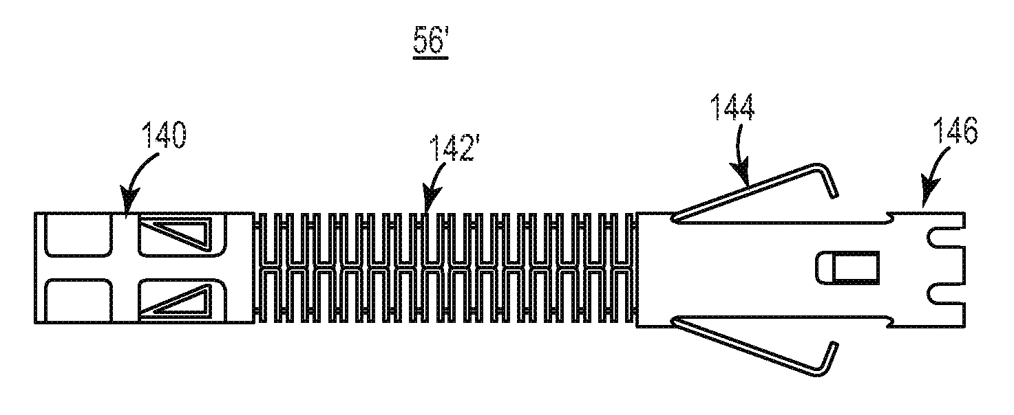
[0012]Yet other aspects in accordance with principles of the present disclosure relate to a method of percutaneously deploying a stented prosthetic heart valve to an implantation site. The method includes receiving a delivery device loaded with a radially expandable prosthetic heart valve having a stent frame to which a valve structure is attached. The delivery device includes a delivery sheath containing the prosthetic heart valve in a compressed arrangement over an inner shaft assembly in a delivery state of the device. Further, the delivery device includes a release assembly having a base, a retraction member, a release member, and a retention member. The base is coupled to the inner shaft assembly. The retraction member extends distal the base and is forced to an extended condition. The release member extends distal the retraction member and is forced to a compressed arrangement in which the release member engages the inner shaft assembly to retain the retraction member in the extended condition. The retention member extends distal the release member and is disposed over a post of the prosthetic heart valve. The prosthetic heart valve is delivered in the compressed arrangement through a bodily lumen of a patient and to the implantation site via the delivery device in the delivery state. The delivery sheath is proximally retracted from the prosthetic heart valve and the retention member. The post is permitted to release from the engagement structure including the release member self-transitioning to a normal, expanded condition and the retraction member self-retracting to a relaxed, retracted condition to proximally withdraw the retention member from the post. With this technique, the separate release and retraction members independently provide sheath sensing and retraction functions, minimizing possible malfunctions of the release assembly.

Problems solved by technology

Traditional open surgery inflicts significant patient trauma and discomfort, and exposes the patient to a number of potential risks, such as infection, stroke, renal failure, and adverse effects associated with the use of the heart-lung bypass machine, for example.
Although transcatheter techniques have attained widespread acceptance with respect to the delivery of conventional stents to restore vessel patency, only mixed results have been realized with percutaneous delivery and implantation of the more complex prosthetic heart valve.
If the prosthesis is incorrectly positioned relative to the native annulus, serious complications can result as the deployed device can leak and may even dislodge from the native valve implantation site.
While, in theory, retaining a partially deployed prosthetic heart valve to the delivery device is straightforward, in actual practice the constraints presented by the stented prosthetic heart valve render the technique exceedingly difficult.
Conversely, this same component cannot be overly rigid so as to avoid damaging the transcatheter heart valve during deployment.
While viable, conventional delivery device designs robustly engage the prosthetic heart valve within the capsule; this robust engagement facilitates the partial deployment technique described above, but the prosthetic heart valve may undesirably catch on the inner engagement structure when full deployment is intended and / or numerous, complex components are required to ensure complete deployment.
Unfortunately, existing delivery device designs cannot consistently meet this preference.

Method used


Image

  • Transcatheter Prosthetic Heart Valve Delivery Device With Passive Trigger Release
  • Transcatheter Prosthetic Heart Valve Delivery Device With Passive Trigger Release
  • Transcatheter Prosthetic Heart Valve Delivery Device With Passive Trigger Release

Examples


Embodiment Construction

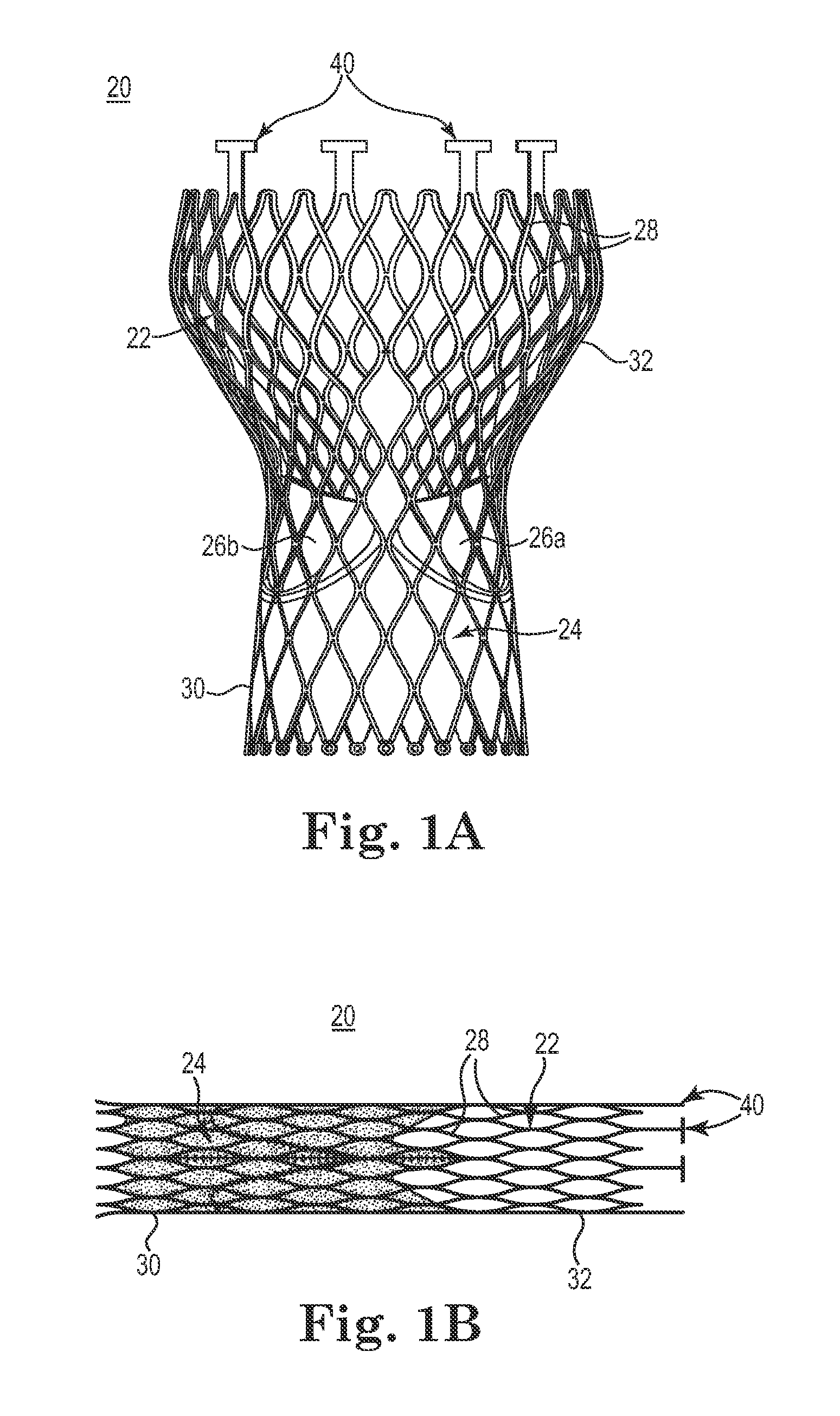
[0030]As referred to herein, stented transcatheter prosthetic heart valves useful with and / or as part of the various systems, devices, and methods of the present disclosure may assume a wide variety of different configurations, such as a bioprosthetic heart valve having tissue leaflets or a synthetic heart valve having polymeric, metallic, or tissue-engineered leaflets, and can be specifically configured for replacing any heart valve. Thus, the stented prosthetic heart valve useful with the systems, devices, and methods of the present disclosure can be generally used for replacement of a native aortic, mitral, pulmonic, or tricuspid valve, for use as a venous valve, or to replace or restore a failed bioprosthesis, such as in the area of an aortic valve or mitral valve, for example.

[0031]In general terms, the stented prosthetic heart valves of the present disclosure include a stent or stent frame maintaining a valve structure (tissue or synthetic), with the stent having a normal, exp...


PUM


Abstract

A delivery device for percutaneously deploying a prosthetic valve includes a sheath, an inner shaft, and a release assembly. The release assembly is disposed between the sheath and the inner shaft, and includes a retraction member, a release member, and a retention member. The retraction member can self-retract in length from an extended condition to a retracted condition. The release member can self-expand from a compressed condition to an expanded condition. The retention member is distal the release member. In a delivery state, the sheath end is distal the retention member, the release member is in the compressed condition and the retraction member in the extended condition to retain the prosthesis. In a deployment state, the sheath end is positioned to permit the release member to self-transition to the expanded condition, allowing the retraction member to self-transition to the retracted condition and release the prosthesis.

Description

CROSS-REFERENCE TO RELATED APPLICATIONS[0001]This application claims priority under 35 U.S.C. §119(e)(1) to U.S. Provisional Patent Application Ser. No. 61 / 328,230, filed Apr. 27, 2010, entitled “Transcatheter Prosthetic Heart Valve Delivery Device with Passive Trigger Release”, and bearing Attorney Docket No. P0036420.00 / M190.374.101; the entire teachings of which are incorporated herein by reference.BACKGROUND[0002]The present disclosure relates to systems, devices, and methods for percutaneous implantation of a prosthetic heart valve. More particularly, it relates to delivery systems, devices, and methods for transcatheter implantation of a stented prosthetic heart valve.[0003]Diseased or otherwise deficient heart valves can be restored, repaired or replaced with an implanted prosthetic heart valve. The terms “repair,”“restore,” and “replace” are used interchangeably throughout this specification, and reference to “restoring” a defective heart valve is inclusive of implanting a p...

Claims


Application Information

Patent Timeline
IPC IPC(8): A61F2/24
CPCA61F2/2418A61F2/2436A61F2230/008A61F2230/0054A61F2002/9505
Inventor DWORK, JOSHUASTANTE, GLENNSHIPLEY, ADAM
Owner MEDTRONIC INC
Learn More