Method and system of on-tool and on-site mfc optimization providing consistent response

a mass flow controller and optimization method technology, applied in the field of mass flow controllers, can solve the problems of not being able to calibrate a mfc for many gases, unable to calibrate a mfc with each specific operating gas, and unable to achieve consistent and accurate response, and short response time

Active Publication Date: 2011-10-27
HITACHI METALS LTD
View PDF7 Cites 13 Cited by
  • Summary
  • Abstract
  • Description
  • Claims
  • Application Information

AI Technical Summary

Benefits of technology

[0004]Several embodiments of the proposed invention provide a consistent and more optimal response from the MFC across multiple operating gases and operating conditions such as, but not limited to, multiple desired flow rates and pressures. One embodiment comprises performing one or more calibration runs on the MFC to ensure a quicker response time. During the one or more runs, the MFC collects required information, calculates optimal tuning parameters for each step of the process, and saves optimal parameters into a MFC memory. Then, during operation, optimal tuning parameters may be retrieved from the MFC memory as needed and used for MFC operation to provide a more consistent and accurate response. One method is adapted for use with a quick or fast-response MFC mode.
[0005]One method comprises performing a MFC optimization run to obtain an initial adjusted mass flow controller valve start position that decreases MFC delay and eliminates or reduces overshoot. The initial adjusted MFC valve start position may comprise an initial valve setting for a particular gas and operating conditions. Multiple adjusted mass flow controller valve start positions may be obtained and saved to the MFC for each gas and / or operating condition in the application process.

Problems solved by technology

Therefore, MFC performance is currently guaranteed only for N2, and MFC performance may significantly degrade when the MFC is used with other gases.
Calibrating MFCs with each specific operating gas is not possible due to the high cost of doing so.
Furthermore, it may not be possible to calibrate a MFC for many gases due to the gas properties.
For example, some gases may be toxic or highly flammable.
Also, calibrating a MFC with a “surrogate” gas having properties similar to the operating gas properties, but without the unwanted gas properties may not be possible or effective for many gas types.

Method used


Image

  • Method and system of on-tool and on-site mfc optimization providing consistent response
  • Method and system of on-tool and on-site mfc optimization providing consistent response
  • Method and system of on-tool and on-site mfc optimization providing consistent response

Examples


Embodiment Construction

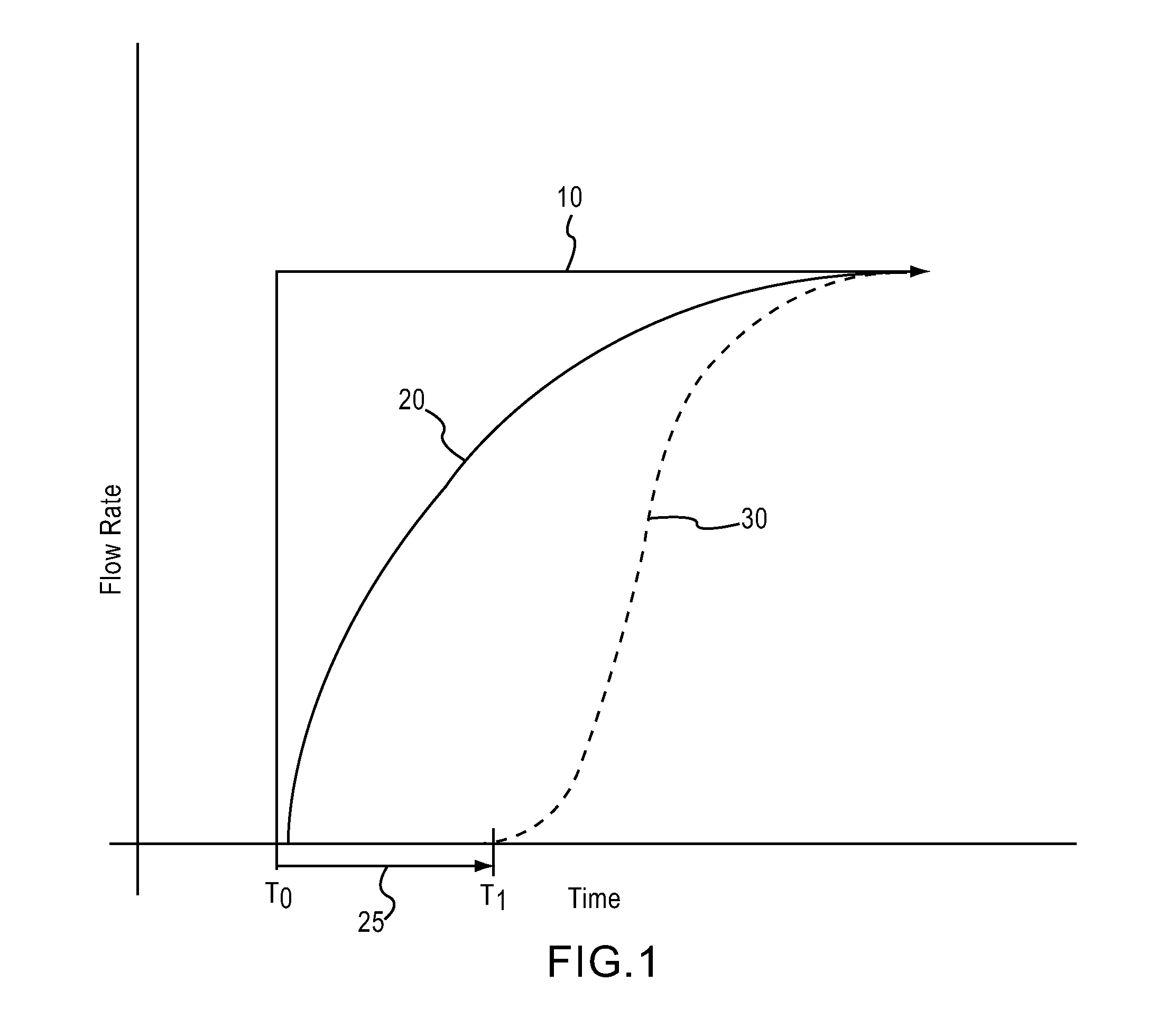
[0021]Seen in FIG. 1 is a graph displaying the difference between a desired mass flow rate 10, also known as a setpoint or a desired flow rate setpoint, an expected mass flow rate 20, also known as an expected flow rate transient, and an actual mass flow rate 30, or actual flow rate transient. At time T0, a desired flow rate setpoint value is given to a MFC. For example, the setpoint may be entered into a MFC control system. Upon initiation of the MFC such as, but not limited to, a control system comprising a quick-response MFC mode, and in response to the desired flow rate setpoint value being entered into the MFC control system, among other operating conditions, the control system is adapted to change the flow rate over time from the original flow rate, at T0, to the desired flow rate setpoint 10 along the expected flow rate transient 20 seen in FIG. 1. However, the actual flow rate through a MFC is not equal to the expected flow rate transient 20, but resembles the actual flow ra...


PUM


Abstract

One method of obtaining an initial adjusted mass flow controller valve start position comprises obtaining a mass flow controller delay period and setting a mass flow controller valve to an initial valve opening position that is less than an expected optimal valve opening position. An initial desired flow rate and initial operating conditions are input into a control system that is in communication with the valve, and the control system is initiated. The control system is adapted to adjust the valve opening position to achieve the initial desired flow rate, while taking into account flow rate and valve position feedback to the control system. During operation of the MFC and control system, the valve position and the flow rate are recorded in one embodiment and a flow rate that one of meets and exceeds a threshold is detected. An initial-flow time-period extending from the time of control system initiation to detection of the threshold being one of met and exceeded is determined and the mass flow controller delay period from the initial flow time period is subtracted from the initial-flow time-period to obtain an adjusted start time. The valve opening position at the adjusted start time is set as the initial adjusted mass flow controller valve start position.

Description

FIELD OF THE INVENTION[0001]The present invention relates generally to mass flow controllers. In particular, but not by way of limitation, the present invention relates to methods and systems for optimizing a mass flow controller across gas types and operating conditions.BACKGROUND OF THE INVENTION[0002]Mass flow controllers (MFCs) having a quick-response (also known as fast-response) mode are currently used in many applications in the semiconductor and other industries. Applications in these industries not only require MFC modes that operate quickly, but the applications also require that the MFCs limit overshoot of a desired mass flow rate. Furthermore, MFC quick-response modes need to provide consistent responses across varying flow conditions throughout various steps of the MFC process. For example, it would be beneficial in certain applications that MFCs produce quick and accurate flow rates across varying pressures for various setpoints and across multiple gases for multi-gas ...

Claims


Application Information

Patent Timeline
Patent Type & Authority Applications(United States)
IPC IPC(8): G05D7/06G05D7/00
CPCG05D7/0635G05D7/06
Inventor SMIRNOV, ALEXEI V.
Owner HITACHI METALS LTD
Why Eureka
Try Eureka