Implant Device and Method for Manufacture

a manufacturing method and implant technology, applied in the field of implant devices and methods for manufacture, can solve the problems of loss of valuable bone stock, increased manufacturing costs, and increased manufacturing costs, and achieve the effects of reducing the cost of manufacturing, and increasing the cost of manufacturing

Inactive Publication Date: 2011-11-03
CONFORMIS
View PDF7 Cites 158 Cited by
  • Summary
  • Abstract
  • Description
  • Claims
  • Application Information

AI Technical Summary

Benefits of technology

[0009]The disclosures herein provide systems and methods for designing, manufacturing and implanting orthopedic implants. Various methods include obtaining a three-dimensional image of a patient's joint, selecting a standard blank implant and modifying the blank to incorporate features that are specific and/or desirable to that patient. Various embodiments provide methods for making implants suitable for a joint, including providing a blank with a (i.e., at least one) dimension smaller than the desired implant size and/or shape, and material is added to the blank so as to form surface or other details on the implant. In related embodiments, adding material to the blank may include laser sintering and/or electron beam melting. Adding material to the blank may include adding ceramic(s), metal(s) and/or ceramic-metal composite(s). The material added to the blank may be polished. In further embodiments, the blank may be made of, e.g., polymer(s), metal(s), cross-linked polymer(s), ceramic(s), ceramic-metal composite(s), and/or alloy(s); or use-appropriate combinations thereof. Providing the blank may include forming the ...

Problems solved by technology

Traditional implant manufacturing processes, which may even include manual steps, and which may be satisfactory for less complex shaping, are becoming inadequate.
The drawback to this approach is that typically a decision must be made between devices that are either too large or too small or otherwise just not the right shape for the patient's anatomy.
Furthermore, joint implants, such as a knee implant that includes tibial and femoral components, often require a relatively large cut on, for example, the tibia.
Such cuts can often be hig...

Method used


Image

  • Implant Device and Method for Manufacture
  • Implant Device and Method for Manufacture
  • Implant Device and Method for Manufacture

Examples


Embodiment Construction

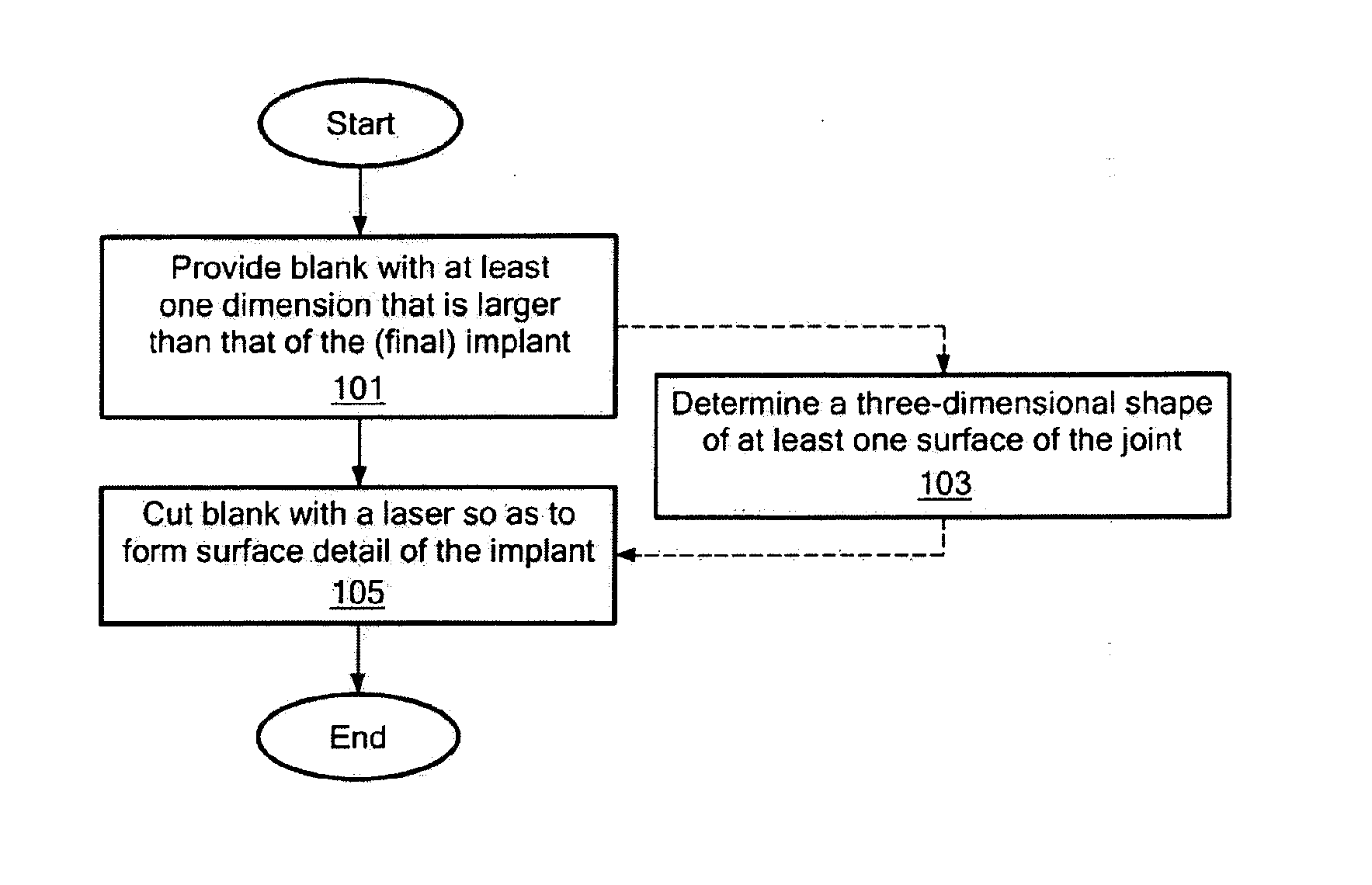
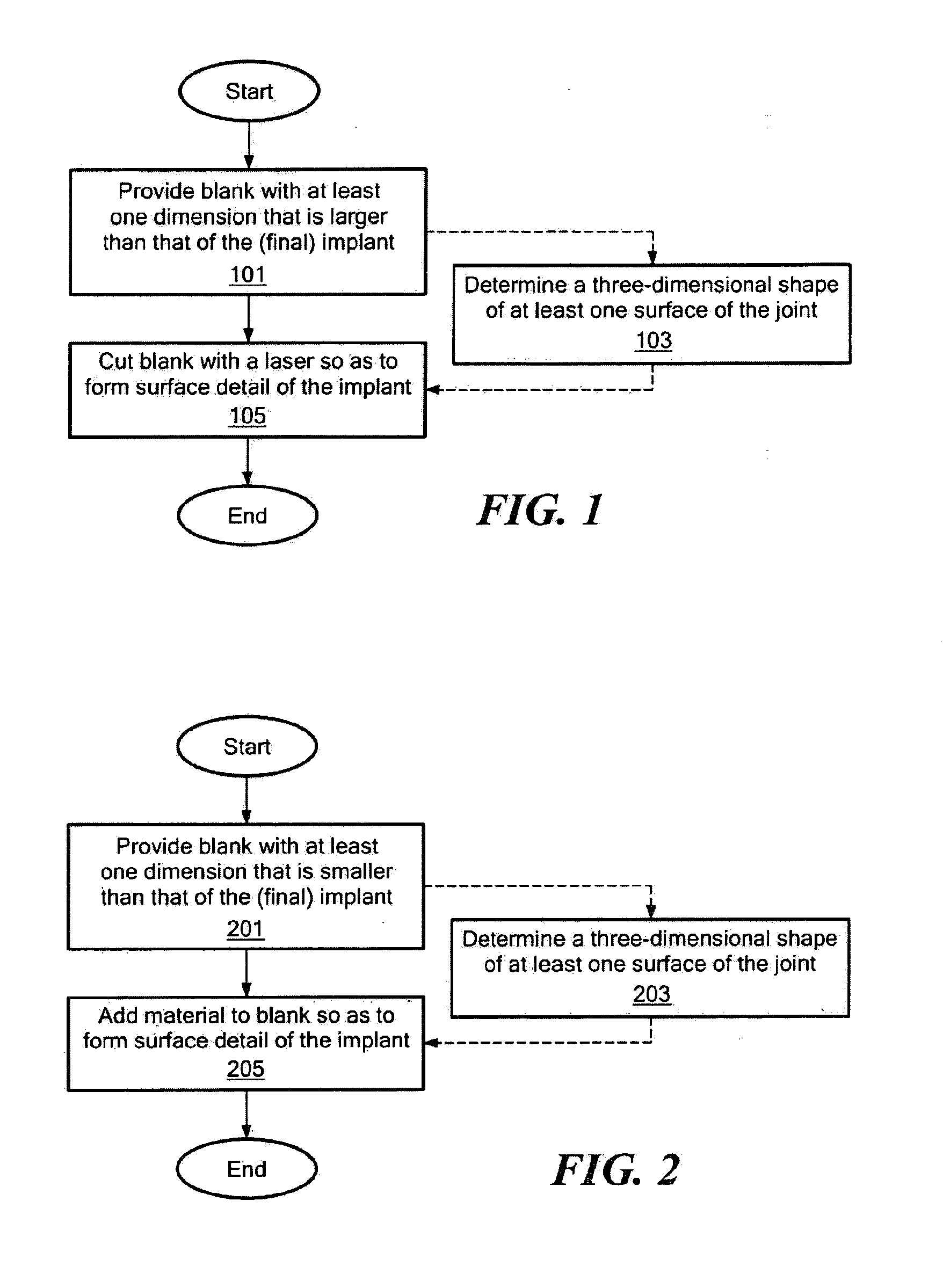
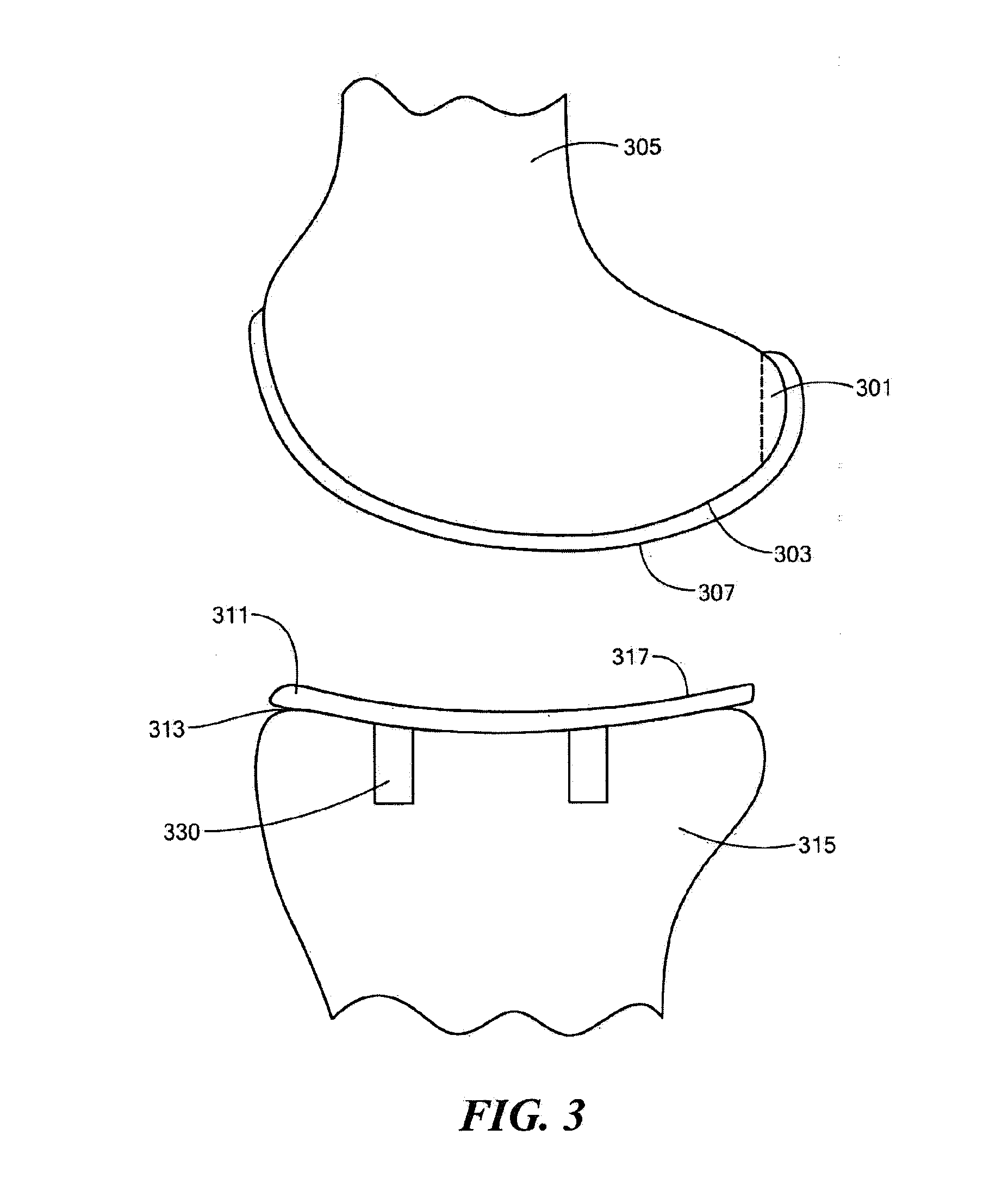
[0034]Disclosed are systems and methods for making joint implants that leverage additive or subtractive manufacturing methods including laser sintering and electron beam melting, and to less-invasive and / or non-invasive joint implants which may be advantageously made by the methods described herein. Such implants may feature a surface of the implant that is advantageously a mirror image of, substantially a negative of or formed in a shape that substantially conforms to the joint surface, or combinations thereof. In other embodiments, non-invasive or less-invasive joint implants that rest on substantially uncut subchondral bone are described. Detailed disclosures are now described in further detail, below.

[0035]As used herein and in the appended claims, the singular forms “a”, “an”, and “the” include plural references unless the context clearly dictates otherwise. Thus, for example, reference to “a device” includes a plurality of such devices and equivalents thereof known to those sk...


PUM

PropertyMeasurementUnit
Sizeaaaaaaaaaa
Shapeaaaaaaaaaa

Abstract

Disclosed are systems, devices and methods for optimizing the manufacture and/or production of patient-specific orthopedic implants. The methods include obtaining image data of a patient, selecting a blank implant to be optimized for the patient, and modifying the blank implant utilizing techniques disclosed herein to alter specific features of the implant to conform to the patient's anatomy.

Description

CROSS-REFERENCE TO RELATED APPLICATIONS[0001]This application claims the benefit of priority to U.S. Provisional Patent Application No. 61 / 353,386, filed on Jun. 10, 2010, entitled “Production of Patient-Specific Implants,” the disclosure of which is hereby incorporated herein by reference in its entirety.[0002]This application is also a continuation-in-part of copending U.S. patent application Ser. No. 12 / 031,239 filed Feb. 14, 2008, entitled, “Implant Device and Method for Manufacture,” which in turn claims priority to U.S. Provisional Patent Application No. 60 / 889,859, filed on Feb. 14, 2007, entitled “Implant Device and Method for Manufacture,” the disclosures of which are both herein incorporated by reference in their entireties.[0003]All of the above patent applications, as well as patent applications and other references mentioned hereinbelow, are hereby incorporated by reference in their entireties.FIELD OF THE INVENTION[0004]Disclosed are methods, systems and devices of mak...

Claims


Application Information

Patent Timeline
IPC IPC(8): B23K26/38
CPCA61F2/4225A61F2002/30968A61F2310/00023A61F2/4202A61F2/32A61F2/30756A61F2310/00167A61F2310/00131A61F2/3859A61F2310/00029A61F2/38Y10T29/49A61F2310/00017A61F2310/00239A61F2/4261A61F2/28A61F2002/30957A61F2/40A61F2002/30092A61F2/3804A61F2/30942A61F2002/30884A61F2002/3097A61F2310/00203A61F2310/00161A61F2310/00011A61F2/4241A61F2002/30892A61F2002/30952A61F2/44A61F2/389A61F2210/0014A61F2310/00179B33Y80/00
Inventor LANG, PHILIPP
Owner CONFORMIS
Why Eureka
Try Eureka