Bicycle electrical system

a technology of electrical system and bicycle, which is applied in the direction of electric energy management, driver interaction, signal transmission/receiving via power distribution, etc., can solve the problem of difficult wiring installation task, achieve the effect of reducing the length of the wire, facilitating wiring installation, and facilitating operation

Active Publication Date: 2011-11-03
SHIMANO INC
View PDF9 Cites 37 Cited by
  • Summary
  • Abstract
  • Description
  • Claims
  • Application Information

AI Technical Summary

Benefits of technology

[0028]Since the electric power line is a two-wire line, even if an electric component including an electric motor is connected to another electric component, the number of wires is smaller than for a system in which a separate signal line is required for each control signal. Consequently, the task of installing the wiring can be accomplished more easily.
[0029]A bicycle electrical system according to a fifteenth aspect is provided according to the fourteenth aspect, wherein the electric motor control section includes an inverter device. As a result, the electric motor, e.g., a brushless DC motor or an AC motor, can be operated efficiently.
[0030]With the bicycle electrical system, since each of the first, second and third electric components has an electric power line communication section, so long as a control section is provided in any one of the electric components or a control section is connected to one of the electric components, the wiring can work be completed such that a plurality of electric components can be controlled by merely connecting separate electric power lines between the three electric components. Since the electric power lines are only connected between two electric components, the length of the wires is shorter. Since the electric power lines are two-wire lines, the number of wires is smaller than a case in which a separate signal line is required for each control signal. Furthermore, electric components having different functions can be connected using the same two-wire power line. Consequently, the task of installing the wiring can be accomplished more easily.
[0031]Additionally, with the bicycle electrical system, since a first electric component including an electric motor and a second electric component both have an electric power line communication section with which communication can be accomplished through an electric power line, the wiring work can be completed by merely connecting separate electric power lines between the three electric components. Thus, the wiring work can be completed more easily.

Problems solved by technology

Consequently, the task of installing the wiring is difficult.

Method used


Image

  • Bicycle electrical system
  • Bicycle electrical system
  • Bicycle electrical system

Examples


first embodiment

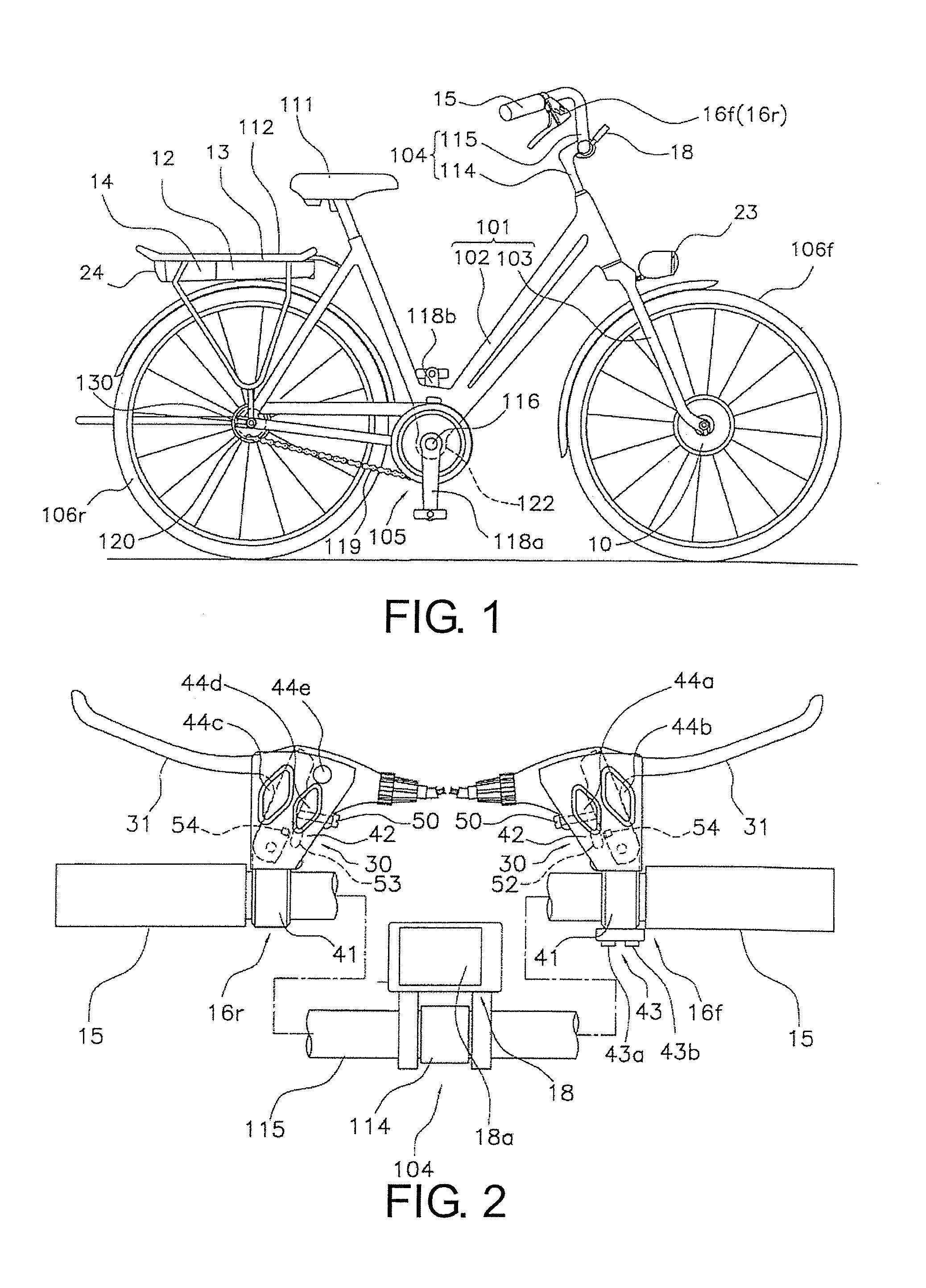
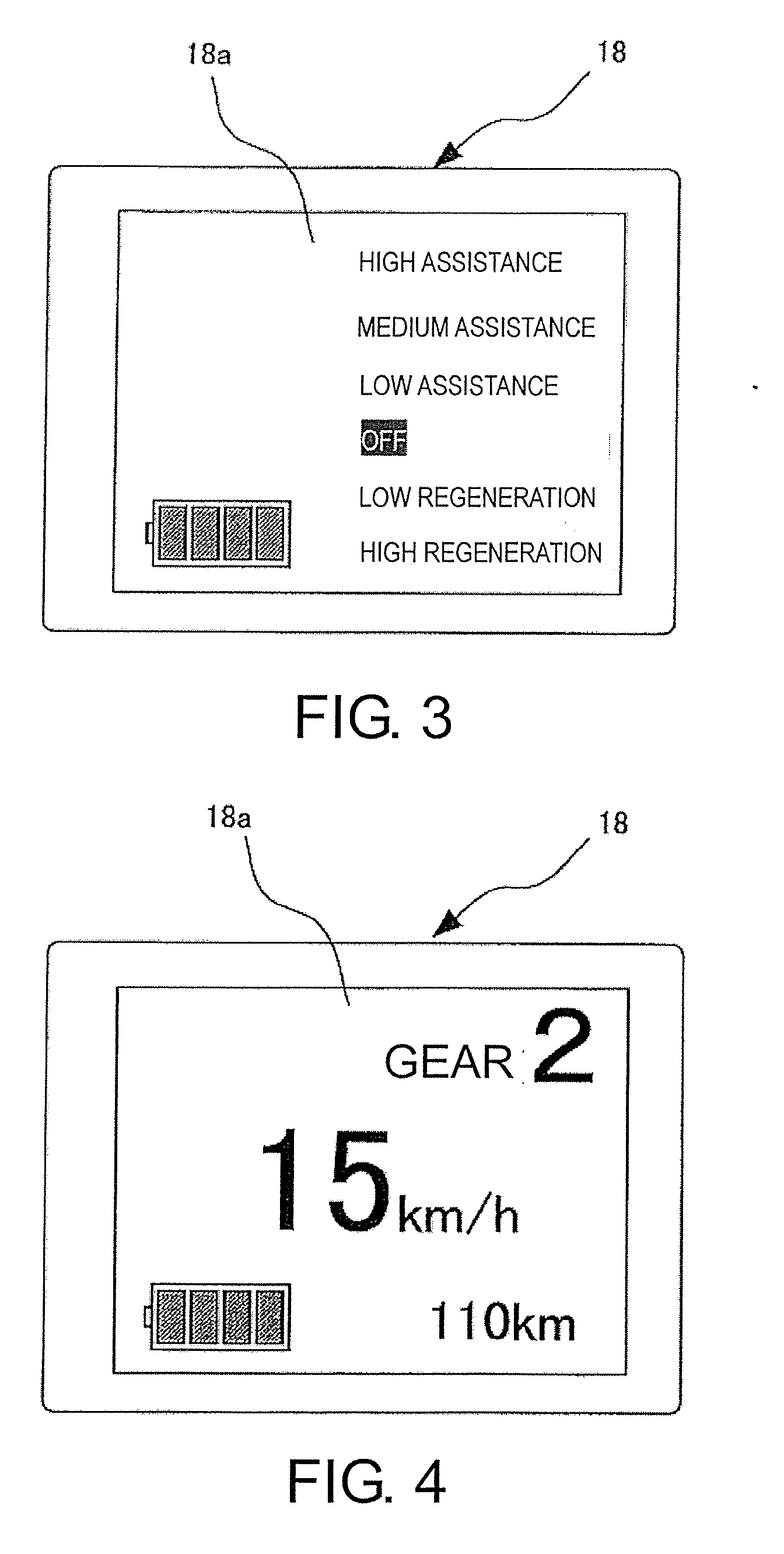
[0049]Referring initially to FIGS. 1 and 6, a bicycle is illustrated that is equipped with a bicycle electrical system 100 (FIG. 6) in accordance with a The bicycle electrical system 100 is configured and arranged such that the task of installing wiring can be accomplished more easily. The bicycle electrical system 100 includes, among other electrical components, a motor unit 10, a control section 12, a rear carrier unit 13, a battery 14, a torque sensor 17, a display device 18, a rotational sensor 19, a gear changing motor 20, a gear position sensor 21, a front headlamp 23 and a tail lamp 24.

[0050]In the illustrated embodiment, the bicycle is configured to assist a rider by using the motor unit 10 to supplement a drive force imparted by the rider. In the illustrated embodiment, the bicycle includes a frame 101 with a frame body 102 and a front fork 103, a handlebar unit 104. The bicycle also includes a drive section 105, a front wheel 106f, a rear wheel 106r, a front brake device ...

sixth embodiment

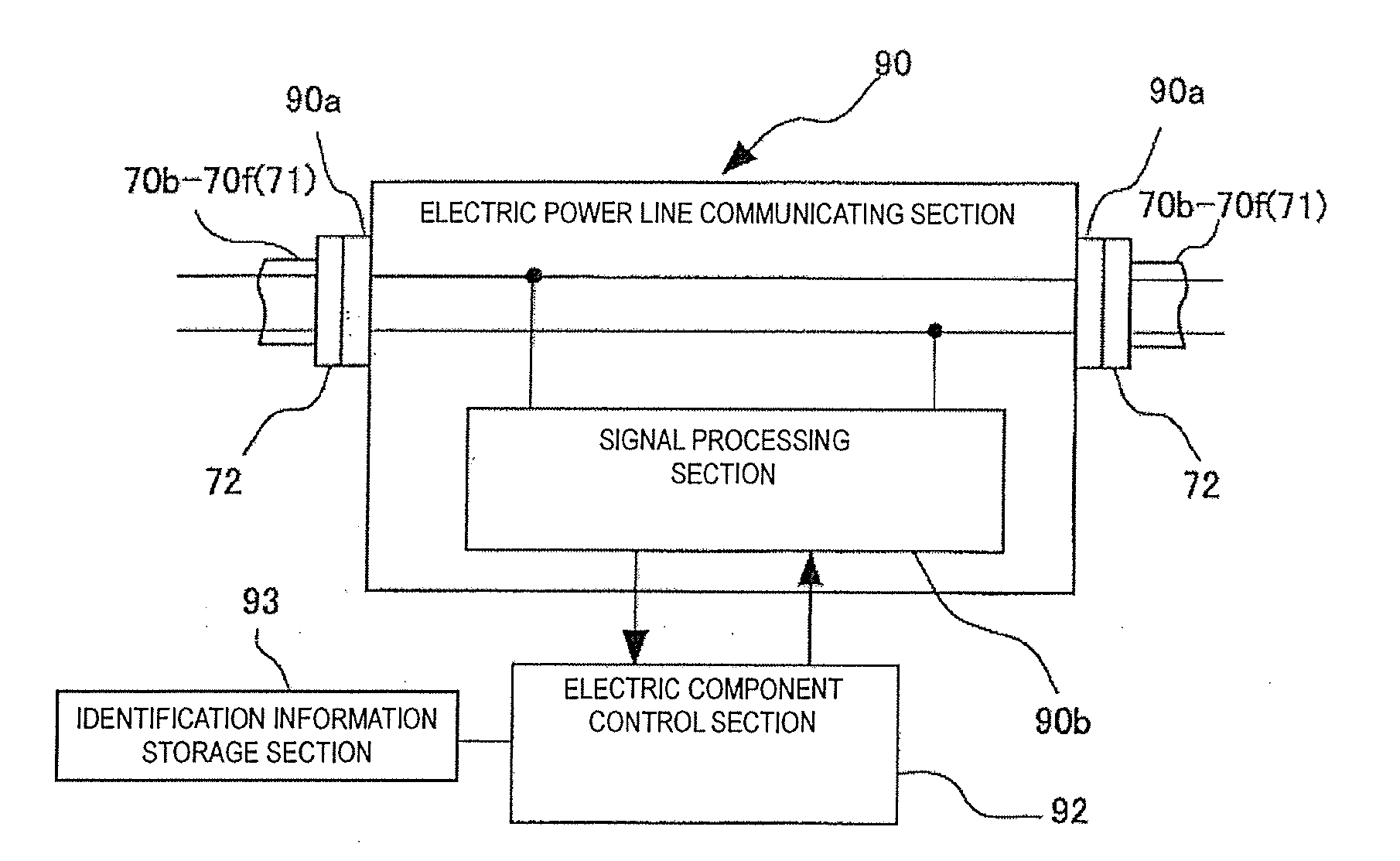
[0079]In a bicycle electrical system 600 the control section 12 is provided in the hanger unit 122a, which corresponds to a second electric component, instead of in the rear carrier unit 13. Only the tail lamp 24 is provided on the rear carrier 112. The electric power line communication section 90 (FIG. 8) is provided on the tail lamp 24 via the electric power line connecting section 90a, which is depicted with small rectangles without a reference numeral in FIG. 14. Thus, the tail lamp 24 is also connected to the hanger unit 122a with the electric power line 70a. If the bicycle does not have a rear carrier, then the tail lamp 24 can be provided on a fender or a seat stay. It is acceptable for the battery 14 to be detachably mounted to the control section 12 or detachably fixed to the seat stay.

[0080]In such a case, the length of the electric power line 71 is shorter because the distance from the rear carrier 112 to the front wheel 106f is shorter. Also, it is more difficult for th...


PUM


Abstract

A bicycle electrical system is provided with a first electric component, a second electric component, and a third electric component. The first electric component includes a first electric power line communication section. The second electric component includes a second electric power line communication section. The third electric component includes a third electric power line communication section. The first and second electric power line communication sections are connected with a first electric power line such that the first and second electric power line communication sections conduct communications via the first electric power line. The second and third electric power line communication sections are connected with a second electric power line such that the second and third electric power line communication sections conduct communications via the second electric power line.

Description

CROSS-REFERENCE TO RELATED APPLICATIONS[0001]This application claims priority under 35 U.S.C. §119 to Japanese Patent Application No. 2010-104568, filed Apr. 28, 2010. The entire disclosure of Japanese Patent Application No. 2010-104568 is hereby incorporated herein by reference.BACKGROUND OF THE INVENTION[0002]1. Field of the Invention[0003]This invention generally relates to an electrical system. More specifically, the present invention relates a bicycle electrical system that can be installed onto a bicycle.[0004]2. Background Information[0005]In recent years, a number of electric components are installed on bicycles. For example, power assisted bicycles have been developed that are configured to supplement a drive force exerted by a rider with an electric motor. Such power assisted bicycles are provided with electric components that are interconnected as a bicycle electrical system. This bicycle electrical system often includes the electric motor, a torque sensor, a rotation sen...

Claims


Application Information

Patent Timeline
Patent Type & Authority Applications(United States)
IPC IPC(8): G08C19/16B62J11/19
CPCB62K23/02Y02T10/642B62M25/08B62M2025/003H02J13/0003H04B3/544H04B2203/5412H04B2203/5458H04B2203/547B60L1/14B60L7/14B60L7/26B60L11/007B60L11/1803B60L11/1861B60L11/1877B60L15/2009B60L15/2054B60L2200/12B60L2240/12B60L2240/421B60L2240/423B60L2250/12B60L2250/16B60L2250/24Y02T10/7044Y02T10/7005Y02T10/705Y02T90/16Y02T10/7275B62K23/06Y02T10/72B60L50/20B60L50/51B60L50/66Y02T10/64Y02T10/70Y04S40/121Y02E60/00
Inventor NISHIHARA, TAIHEISUZUKI, TAKAFUMIKOU, SHUN
Owner SHIMANO INC
Why Eureka
Try Eureka