Sensor apparatus and information display apparatus

a technology of information display and sensor unit, which is applied in the direction of resistance/reactance/impedence, instruments, computing, etc., can solve the problems of significant restriction of detection distance or sensitivity, and the inability to increase the detection distance of the target object, so as to improve the detection sensitivity of the detection target object by the sensor unit, increase the detectable distance, and stabilize the detection sensitivity

Inactive Publication Date: 2011-11-03
SONY CORP
View PDF16 Cites 35 Cited by
  • Summary
  • Abstract
  • Description
  • Claims
  • Application Information

AI Technical Summary

Benefits of technology

[0013]In the sensor apparatus, on the basis of the change in capacitance of the detection electrodes switched to the first state, the proximity of the detection target object to the sensor unit is detected. A relative distance (first distance) between the sensor unit and the detection target object is calculated by the calculation unit. At this time, the remaining detection electrodes other than the detection electrodes switched to the first state are maintained to be the second state that is the electrically floating state by the switch circuit unit, so the capacitance between the detection electrodes in the first state and the remaining detection electrodes is reduced. Thus, a detection sensitivity for the detection target object by the sensor unit can be improved.
[0014]Further, in the sensor apparatus, at least two detection electrodes having an electrode distance (second distance) corresponding to the first distance are switched from the second state to the first state one by one. As a result, it is possible to ensure a stable detection sensitivity regardless of a proximity distance of the detection target object and increase a detectable distance.

Problems solved by technology

However, the information display apparatus disclosed in Patent Document 1 has a problem in that it may be impossible to increase a distance for the detection of the target object due to the influence of electrostatic binding between the detection electrodes.
Further, the structure disclosed in Patent Document 2 provides a low degree of freedom in terms of the configuration or arrangement of the detection electrodes, so the detection distance or sensitivity is significantly restricted by the size of a detection area.

Method used


Image

  • Sensor apparatus and information display apparatus
  • Sensor apparatus and information display apparatus
  • Sensor apparatus and information display apparatus

Examples


first embodiment

[0043](Sensor Apparatus)

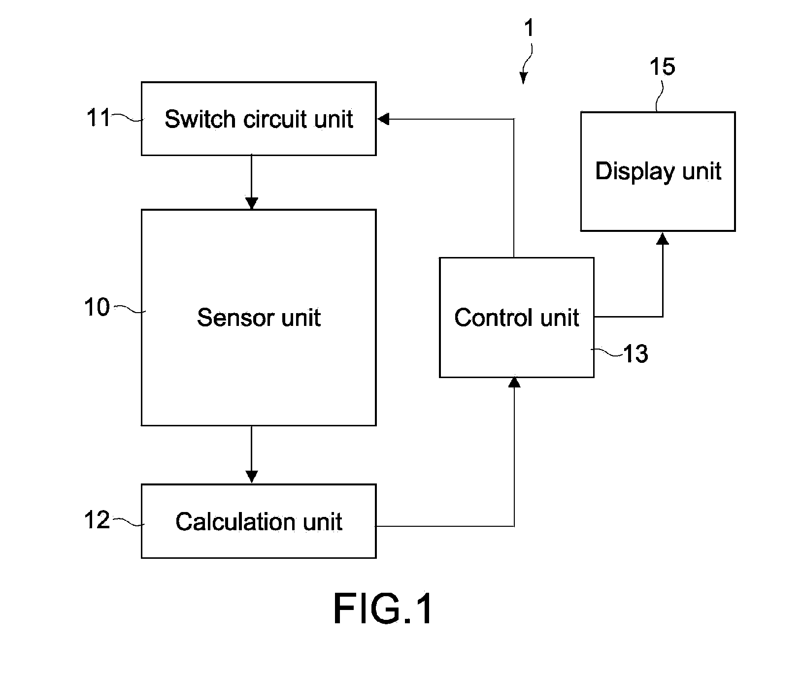
[0044]FIG. 1 is a block diagram showing the structure of a sensor apparatus according to an embodiment of the present invention. A sensor apparatus 1 of this embodiment includes a sensor unit 10, a switch circuit unit 11, a calculation unit 12, a control unit 13, and a display unit 15. The sensor apparatus 1 functions as a detection apparatus of an input coordinate position, for example, and constitutes an input interface of an information display apparatus that controls a display image in accordance with the input coordinate position.

[0045](Sensor Unit)

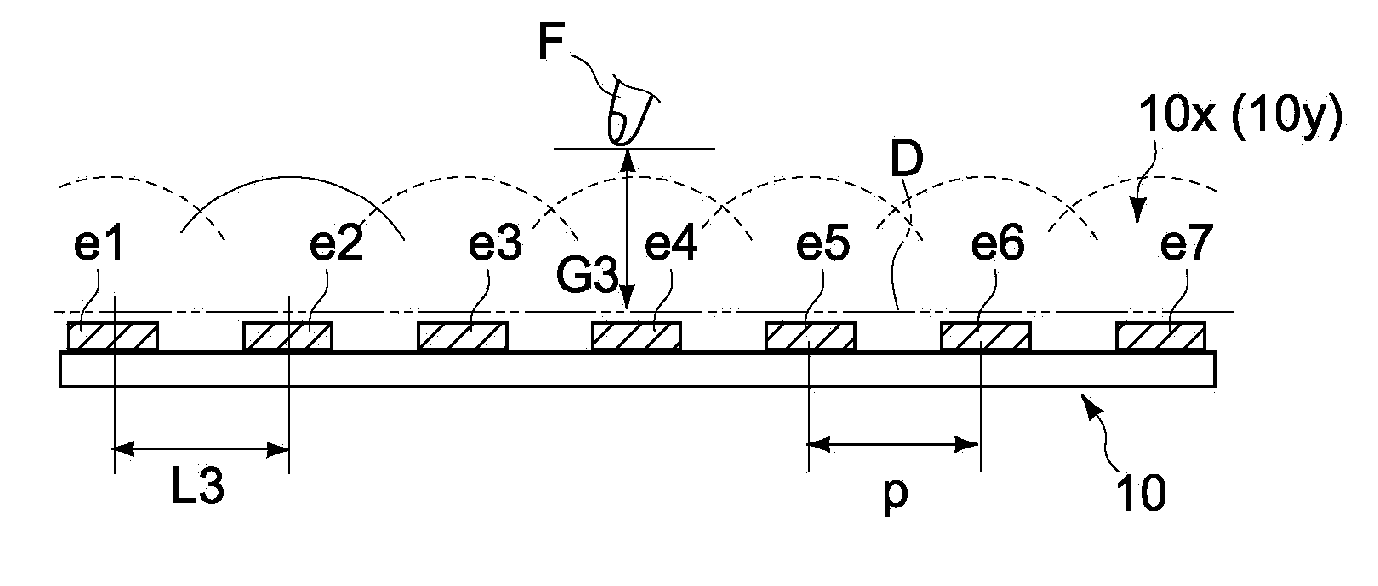
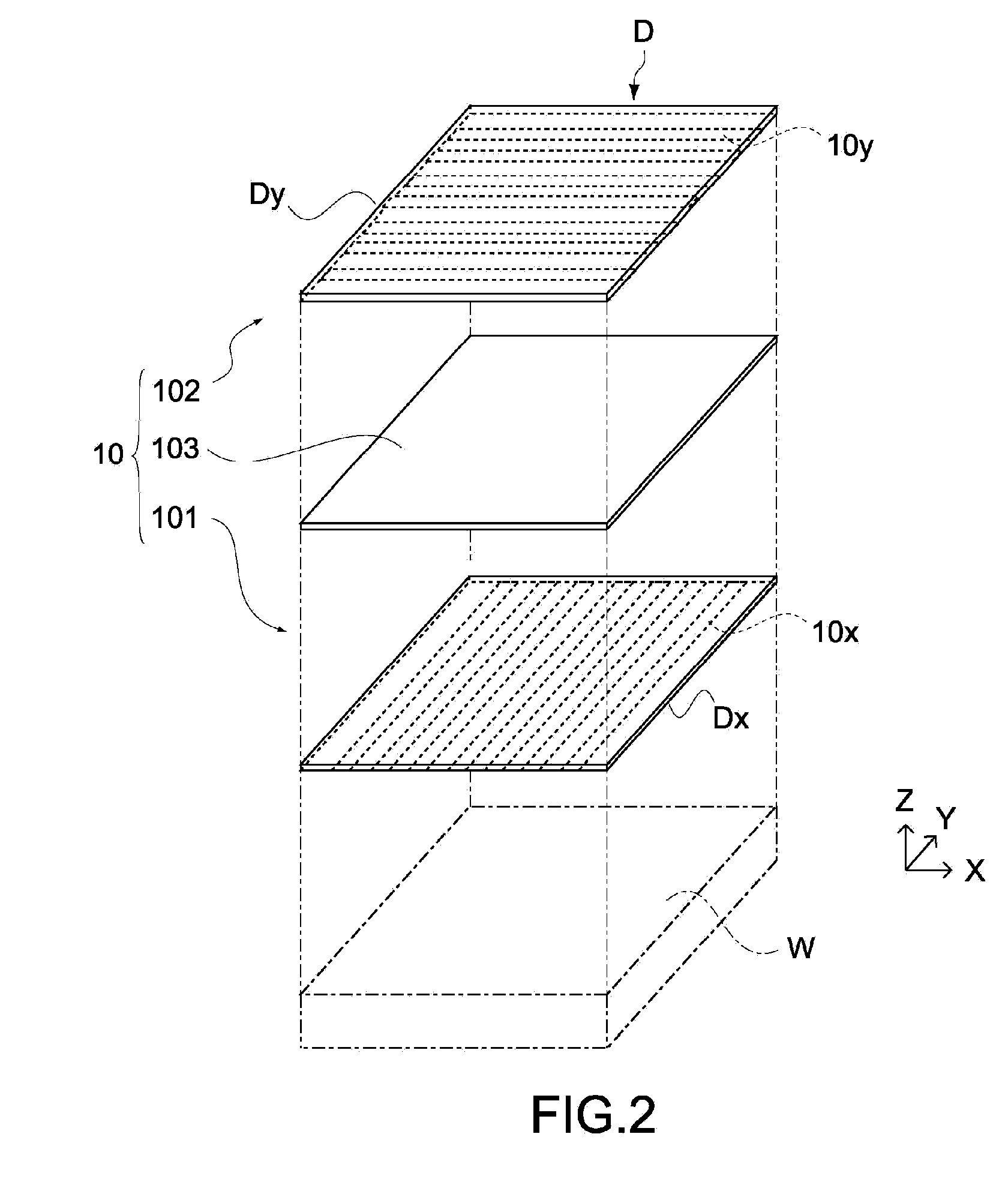
[0046]FIG. 2 is an exploded perspective view showing the schematic structure of the sensor unit 10. The sensor unit 10 has a laminated structure of a first electrode substrate 101, a second electrode substrate 102, and a bonding layer 103, which bonds the electrode substrates 101 and 102 to each other. The sensor unit 10 detects positional coordinates of a detection target object on an XY plane shown in FIG. 2...

second embodiment

[0107]Next, a second embodiment of the present invention will be described. FIG. 11 is a schematic structural diagram of a sensor apparatus according to this embodiment.

[0108]The sensor apparatus of this embodiment has the sensor unit 10 described above and a display device 50. The sensor unit 10 is disposed between two transparent base members 51, and the display device 50 is formed of a liquid crystal panel or an organic EL panel having a display surface for displaying information such as characters or figures, which is disposed so as to be opposed to the back surface of the sensor unit 10. A display image of the display device 50 is controlled on the basis of a detection output of the sensor unit 10. The sensor apparatus according to this embodiment is applied to a mobile information processing terminal typified by a mobile phone. The other structures (switch circuit unit 11, calculation unit 12, and control unit 13) except the sensor unit 10 are stored in the main body of the te...

third embodiment

[0111]FIG. 12 is a schematic structural diagram showing a sensor apparatus according to a third embodiment of the present invention. The sensor apparatus of this embodiment is different from that of the second embodiment in that the display device 50 is disposed so as to be opposed to the front surface of the sensor unit 10. The sensor unit 10 is supported by a chassis 60 disposed in a casing.

[0112]Also in this embodiment, it is possible to detect the finger F in proximity to the sensor unit 10 with high sensitivity. Therefore, even in the case where the display device 50 is intervened between the sensor unit 10 and the finger F, the proximity of the finger and the movement thereof can be detected with high accuracy. Further, according to this embodiment, because the sensor unit 10 is disposed on the back surface side of the display device 50, each of the members does not have to be made of a translucent material, with the result that the degree of freedom for selection of the mater...


PUM


Abstract

A sensor apparatus includes a sensor unit, a calculation unit, a switch circuit unit, and a control unit. The sensor unit has a plurality of detection electrodes each having a capacitance changed by proximity of a detection target object. The calculation unit calculates a first distance, which is a distance between the detection target object and the sensor unit. The switch circuit unit is capable of switching the detection electrodes between a first state in which a signal voltage for detecting the capacitance is supplied and a second state which is an electrically floating state, and selects at least two detection electrodes one by one switched from the second state to the first state. The control unit controls the switch circuit unit to cause a second distance, which is a distance between the detection electrodes switched from the second state to the first state, to correspond to the first distance.

Description

BACKGROUND OF THE INVENTION[0001]1. Field of the Invention[0002]The present invention relates to a sensor apparatus and an information display apparatus that detect the proximity or contact of a detection target object.[0003]2. Description of the Related Art[0004]Generally, a flat-type information display apparatus that uses a liquid crystal display element detects the contact of a finger or the like to a display panel surface with a touch sensor and controls a display image or an operation on the basis of coordinate information of the contact position. In recent years, in addition to the detection of a contact state, an information display apparatus capable of detecting a proximity state before a finger or the like touches a touch sensor has been proposed (see, for example, Japanese Patent Application Laid-open Nos. 2008-117371 and 2008-153025 (hereinafter, referred to as Patent Documents 1 and 2, respectively)).[0005]For example, Patent Document 1 discloses a method for adjusting ...

Claims


Application Information

Patent Timeline
Patent Type & Authority Applications(United States)
IPC IPC(8): G06F3/045G06F19/00
CPCG06F3/0416G06F2203/04101G06F3/044G06F3/04166G06F3/0445G06F3/0446
Inventor TSUKAHARA, TSUBASAITO, OSAMUGOTO, TETSUROKURIYA, SHINOBUNAKAGAWA, TOSHIYUKI
Owner SONY CORP
Why Eureka
Try Eureka