Display apparatus
a technology for displaying apparatus and images, applied in the field of displaying apparatuses, can solve the problems of less low-luminance area, poor gradation of illustration images, and the inability of apparatuses adopting such energy-saving technology to reduce current consumption, so as to reduce current consumption of backlight, reduce image luminance, and improve gradation.
- Summary
- Abstract
- Description
- Claims
- Application Information
AI Technical Summary
Benefits of technology
Problems solved by technology
Method used
Image

Examples
first embodiment
[0039]
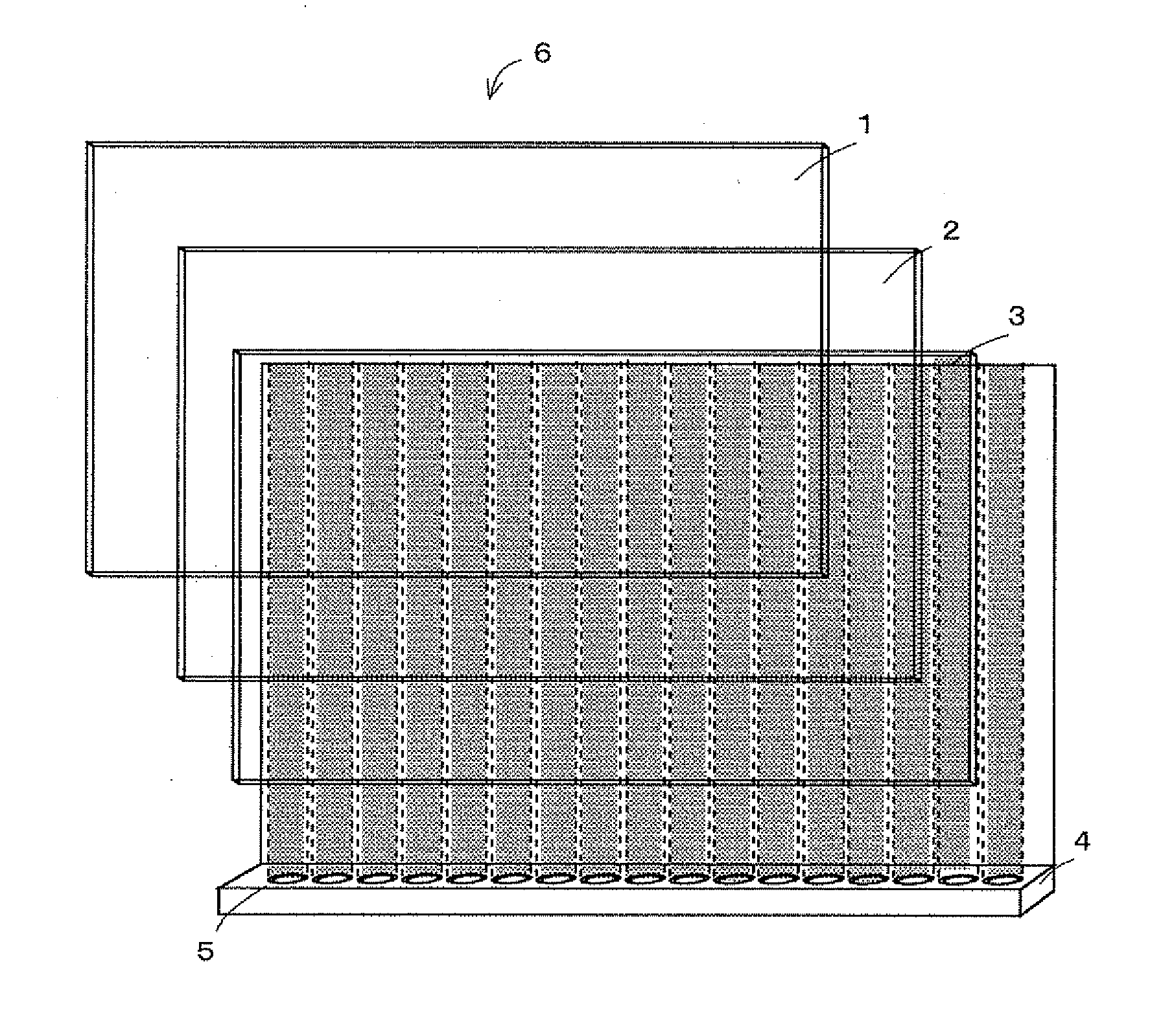
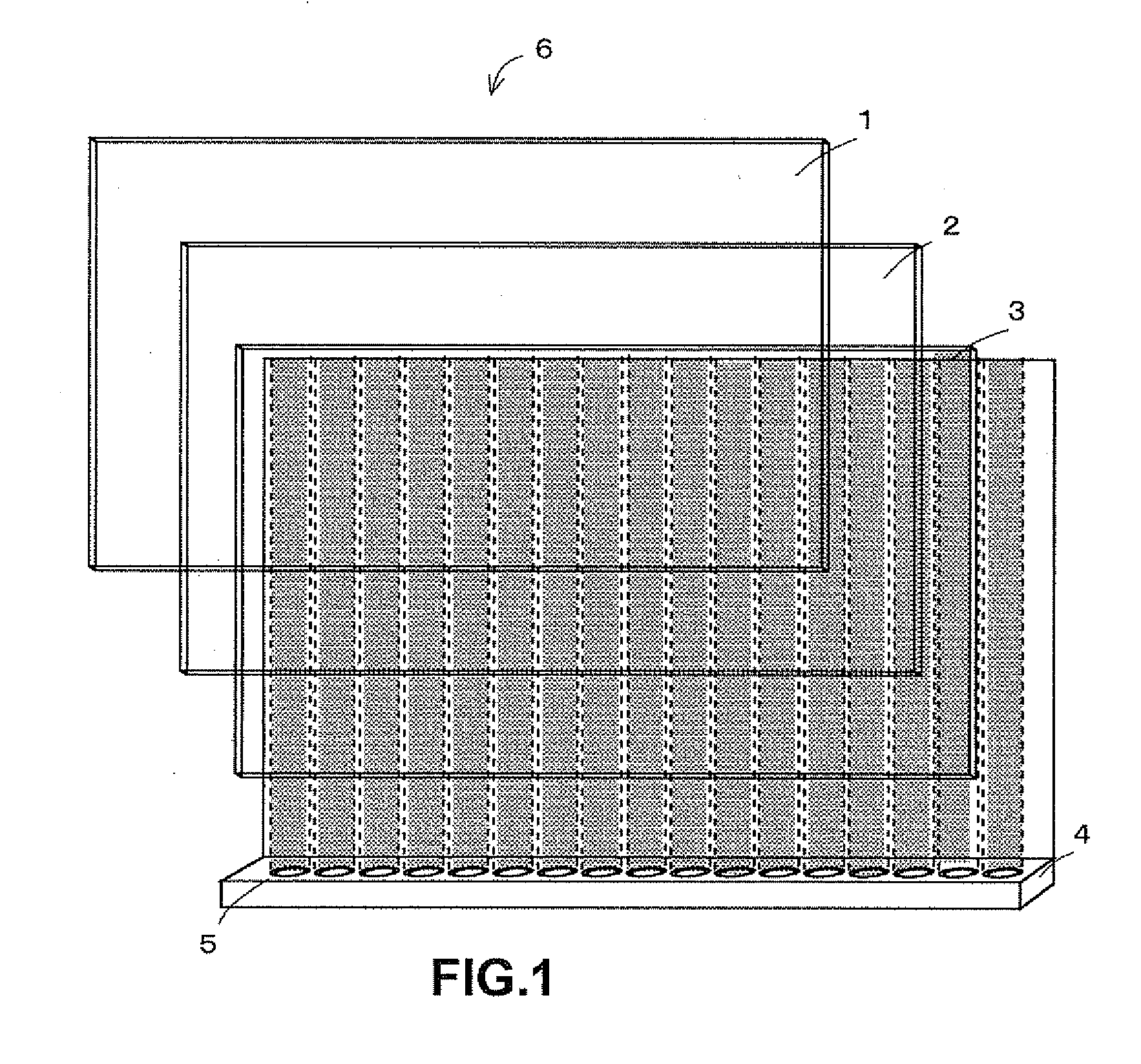
[0040]The configuration of a display included in an on-vehicle apparatus to be installed in a vehicle is described based on FIG. 1. A display 6 includes a color filter 1, a liquid crystal layer 2, a TFT (Thin Film Transistor) 3, and a backlight 4.
[0041]The color filter 1 is a film on which three primary colors (ROB) are printed on each pixel.
[0042]The liquid crystal layer 2 has a function in which molecular arrangement of liquid crystal is changed when voltage is applied from the outside. The liquid crystal layer 2 can be called a crystal shutter.
[0043]The TFT 3 is a thin film transistor including electrodes disposed in a matrix. When an image controller controls electrical current to flow into those electrodes, a voltage generated in cells disposed in a matrix on the TFT 3 changes the molecular arrangement of liquid crystal corresponding to the cells, in the liquid crystal layer 2.
[0044]That is, the TFT 3 has a function of displaying a color corresponding to the part where li...
second embodiment
[0099]So far, the first embodiment was described. Next, a second embodiment that reduces further current consumption is described. Hereafter, the second embodiment is described centering on the part different from the first embodiment because an on-vehicle apparatus 10 of the second embodiment has a similar structure with that of the first embodiment.
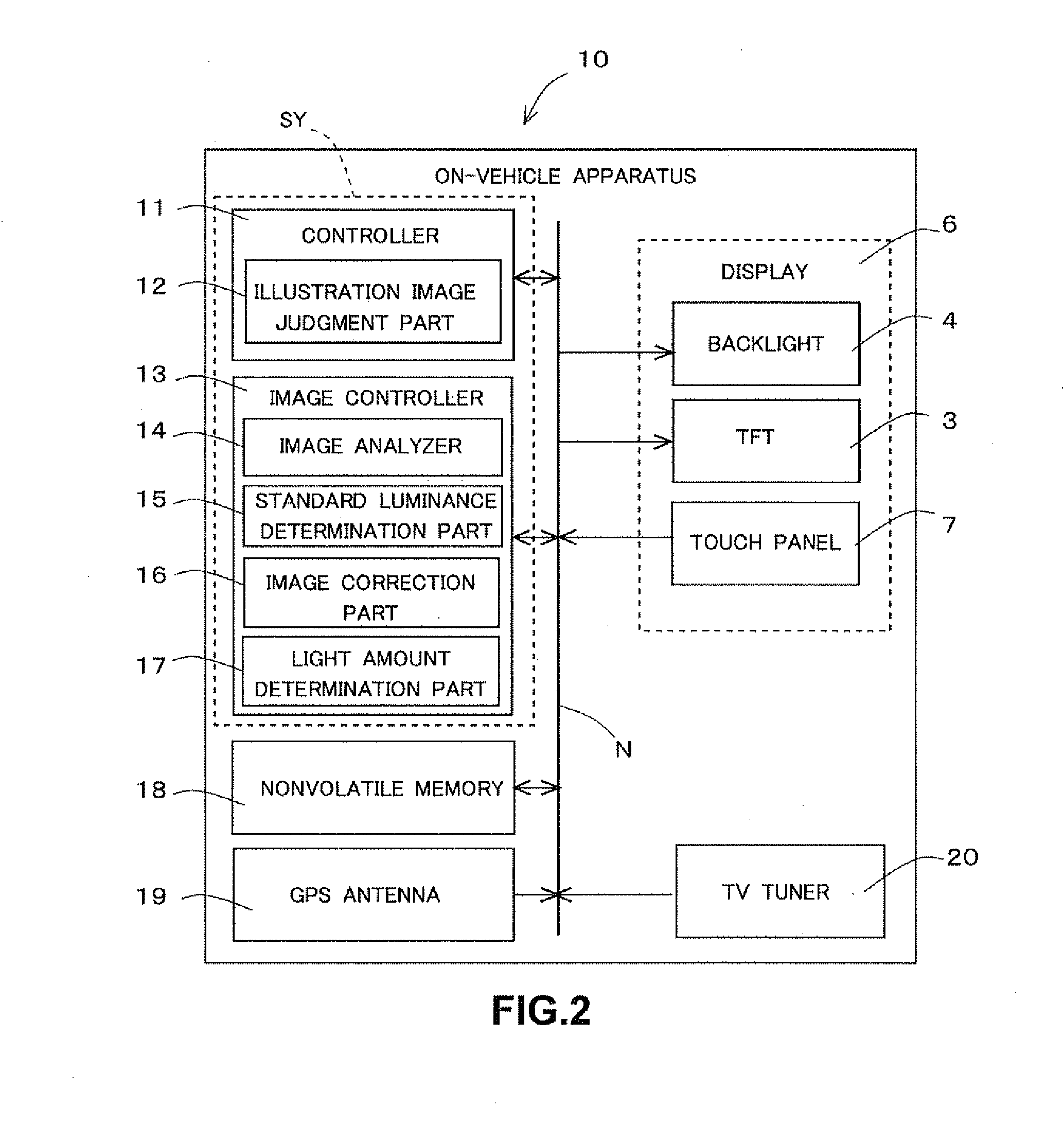
[0100]First, in a step S11 of FIG. 12, an illustration image judgment part 12 of a controller 11 judges whether or not an image to be displayed on a display 6 is an illustration image (the step S11).
[0101]When the image to be displayed is an illustration image (Yes at the step S11), the process moves to a step S12. When the image to be displayed is not judged as an illustration image (No at the step S11), the process moves to a step S14 without implementing the step S12 and a step S13. That is, when the image to be displayed is not judged as an illustration image, the processes of the step S12 and the step S13 are prohibited.
[0102]The d...
third embodiment
[0127]So far, the second embodiment was described. Next a third embodiment that reduces current consumption much further is described. Hereafter, the third embodiment is described centering on the part different from the second embodiment because an on-vehicle apparatus 10 of the third embodiment and that of the second embodiment are of substantially the same structure.
[0128]First, in a step S21 of FIG. 15, an illustration image judgment part 12 of a controller 11 judges whether or not the inputted image is an illustration image (the step S21).
[0129]When the image to be displayed is judged as an illustration image (Yes at the step S21), the process moves to a step S22. When the image to be displayed is not judged as an illustration image (No at the step S21), the process moves to a step S23.
[0130]The description of the processes for display after the process moves to the step S23 in the case of “No” at the step S21 is omitted here because the processes are the normal processes descr...
PUM
 Abstract
Description
Claims
Application Information
 - R&D
- Intellectual Property
- Life Sciences
- Materials
- Tech Scout
- Unparalleled Data Quality
- Higher Quality Content
- 60% Fewer Hallucinations
Browse by: Latest US Patents, China's latest patents, Technical Efficacy Thesaurus, Application Domain, Technology Topic, Popular Technical Reports.
© 2025 PatSnap. All rights reserved.Legal|Privacy policy|Modern Slavery Act Transparency Statement|Sitemap|About US| Contact US: help@patsnap.com