Microscopy Method and Microscope With Enhanced Resolution

a microscopy and microscope technology, applied in the field of enhanced resolution microscopy, can solve the problems of unnecessarily exposed radiation to specimens, marked improvement of resolution below the diffraction limit of the microscope, and invariably limited optical resolution of light microscopes, including those of lsms,

Active Publication Date: 2011-11-03
CARL ZEISS MICROSCOPY GMBH
View PDF9 Cites 78 Cited by
  • Summary
  • Abstract
  • Description
  • Claims
  • Application Information

AI Technical Summary

Benefits of technology

[0020]The invention describes a method by means of which it is possible to generate high-resolution images even for specimens that are more complex than a sp

Problems solved by technology

This does not lead to a markedly improved resolution below the diffraction limit of the microscope.
Due to the laws of physics, the optical resolution of a light microscope, including that of an LSM, is invariably diffraction-limited.
Another disadvantage of this method is that the specimen, in areas outside the detected focus, is unnecessarily exposed to radiation since the necessary structured illumination passes through the entire specimen volume.
Furthermore, this method can currently not be used for thi

Method used


Image

  • Microscopy Method and Microscope With Enhanced Resolution
  • Microscopy Method and Microscope With Enhanced Resolution
  • Microscopy Method and Microscope With Enhanced Resolution

Examples


Embodiment Construction

[0021]The method comprises the following important steps:

[0022]The illumination (an illumination pattern) for detection is shifted with an accuracy that is above the attainable optical resolution.

[0023]During the shift, several images with the highest attainable optical resolution are captured, which images correspond to a certain shift location of the illumination pattern.

[0024]Based on the detected signals, for example, a fluorescent signal, of the individual images, a high-resolution image is calculated.

[0025]Using nonlinear excitation and the relevant fluorescent markers, the resolution can be further enhanced.

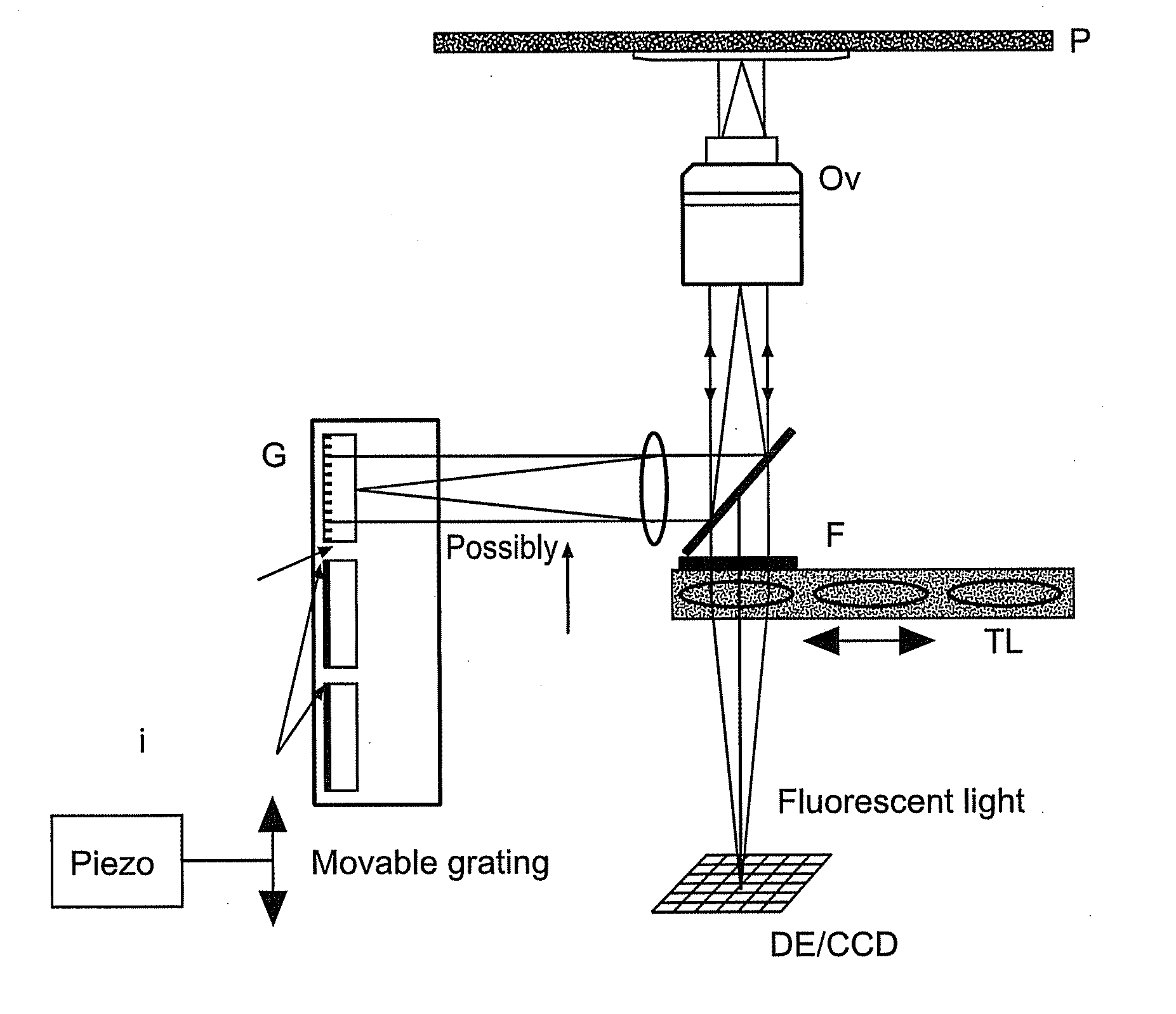
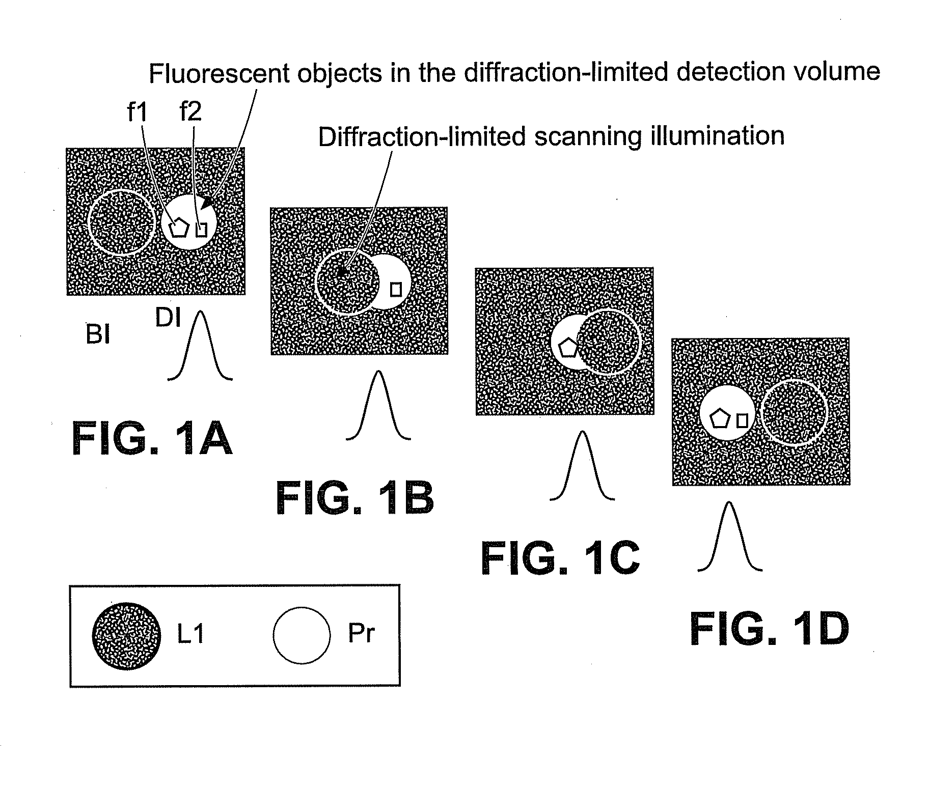
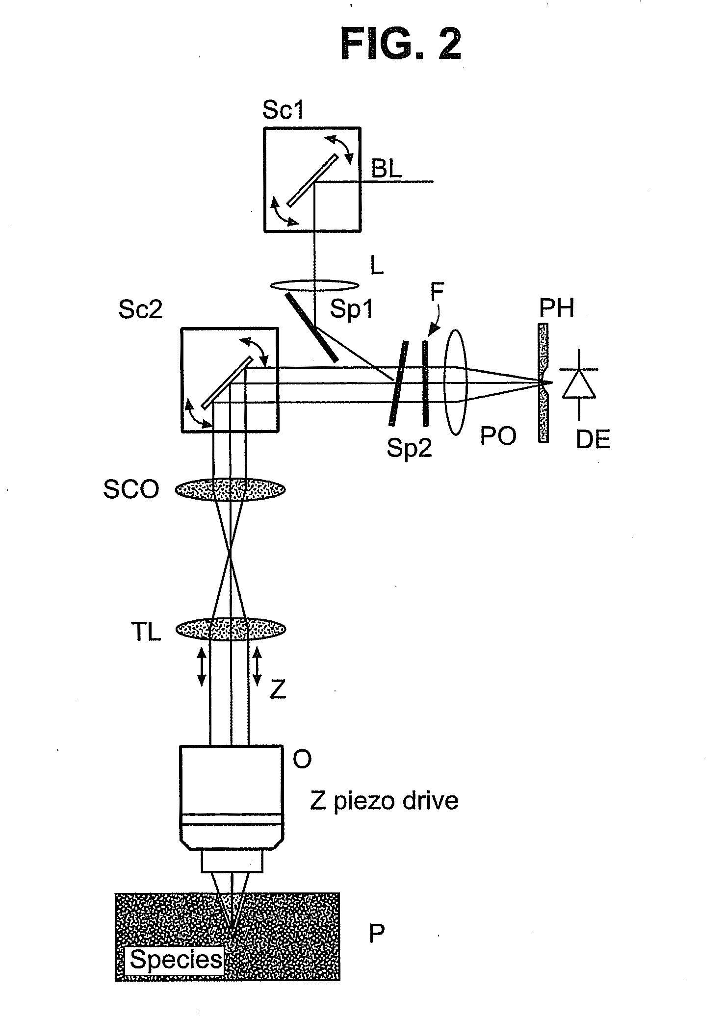
[0026]In FIG. 1a-d), the central idea of the invention is shown with the aid of an illumination spot of a laser scanning microscope.

[0027]It shows how the scan field of a laser scanning microscope (LSM), see also FIG. 2, is moved across the specimen by shifting it with appropriate means (stage motion, second scanner). L1 is the light spot of the LSM that is moved in a defi...


PUM


Abstract

Method for enhancing the resolution of a microscope during the detection of an illuminated specimen and a microscope for carrying out the method, wherein in a first position, an illumination pattern is generated on the specimen, the resolution of which is preferably within the range of the attainable optical resolution of the microscope or higher, wherein a relative movement, preferably perpendicular to the direction of illumination, from a first into at least one second position of the illumination pattern on the specimen is generated at least once between the detection and the illumination pattern with a step width smaller than the resolution limit of the microscope and detection and storage of the detection signals take place both in the first and in the second position.

Description

BACKGROUND OF THE INVENTION[0001]Luminescence microscopy is a classic application of light microscopy for studying biological preparations. To this end, certain dyes (known as phosphores or fluorophores) are used to specifically mark specimens, e.g., cell components. As mentioned [sic], the specimen is illuminated with illuminating radiation that produces excitation radiation [sic] and the thereby excited luminescence radiation is detected with suitable detectors. Normally, the microscope for this purpose comprises a dichroic beam splitter in combination with block filters that separate the luminescence radiation from the excitation radiation and thereby make it possible to observe [the beams] separately. This method makes it possible to visualize individual cell components dyed in different colors under the microscope. It is, of course, also possible for several components of a preparation to be simultaneously dyed with different dyes which accumulate specifically in different stru...

Claims


Application Information

Patent Timeline
IPC IPC(8): G02B21/06
CPCG02B21/0036G02B21/008G02B21/0076G02B21/0072
Inventor KLEPPE, INGONETZ, RALFNOVIKAU, YAUHENI
Owner CARL ZEISS MICROSCOPY GMBH
Why Eureka
Try Eureka