Zoom lens for projection and projection-type display apparatus

Active Publication Date: 2011-11-03
FUJIFILM CORP
View PDF1 Cites 10 Cited by
  • Summary
  • Abstract
  • Description
  • Claims
  • Application Information

AI Technical Summary

Benefits of technology

[0049]Therefore, in the zoom lens for projection of the present invention, the refractive power of the third lens group is greatly reduced to satisfy the formula (1), and correction of aberration is assigned, as a main function, to the third lens group. Further, most of variable magnification function is assigned to the second lens group. Therefore, although the zoom lens for projection of the present invention is a compact lens using a minimum number of aspheric lens, an optical performance that would be achievable by using the two

Problems solved by technology

However, since further reduction in the size of a light output unit in a high luminance light source tends to be difficult, the aforementioned measures are difficult to be taken.
Consequently, the cost increases.
Therefore, the cost greatly increases.
Further, when the number of movable lens groups for changing magnification is increased to three or greater to lower the F-number of the zoom lens, the cost for production of the

Method used


Image

  • Zoom lens for projection and projection-type display apparatus
  • Zoom lens for projection and projection-type display apparatus
  • Zoom lens for projection and projection-type display apparatus

Examples


example 1

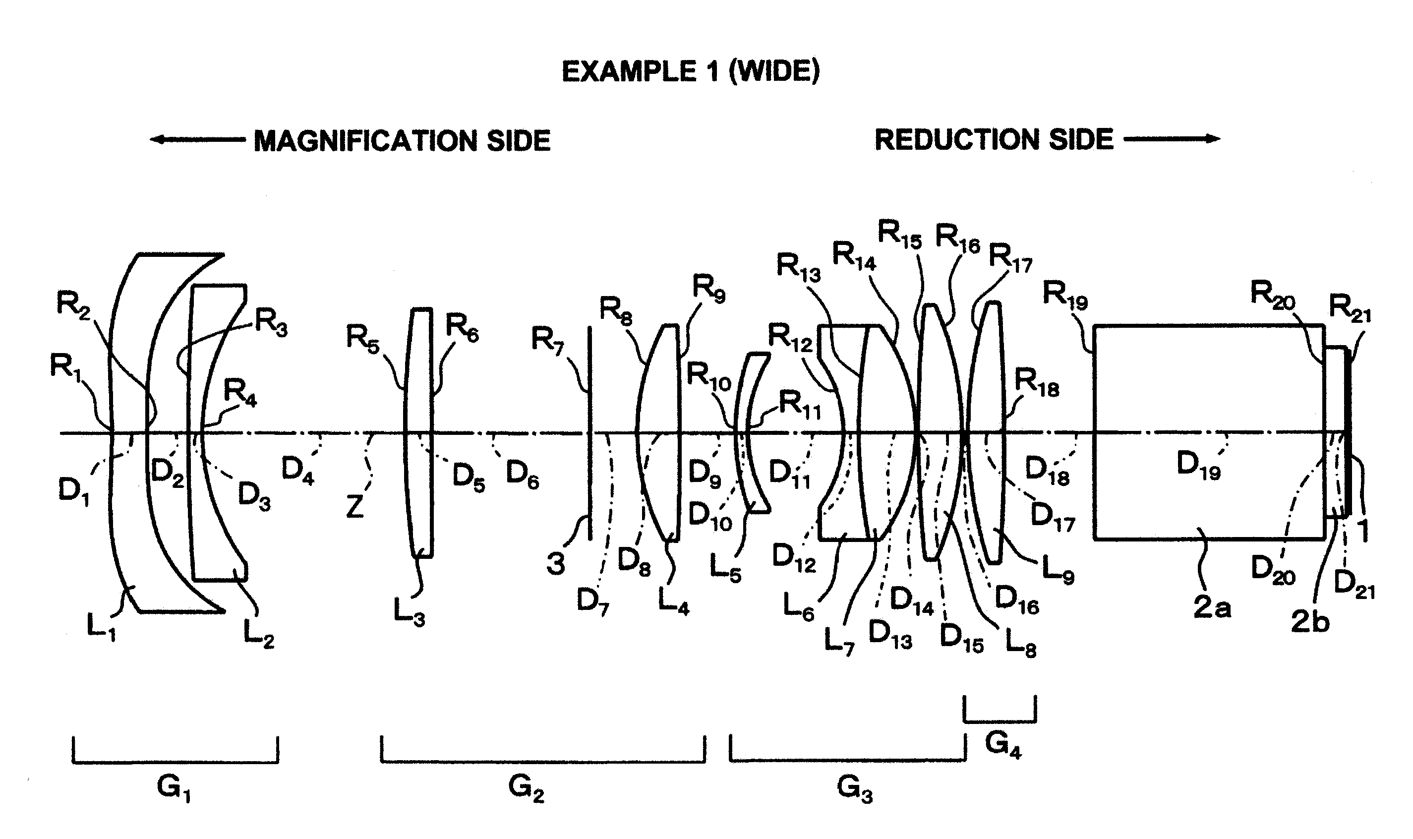
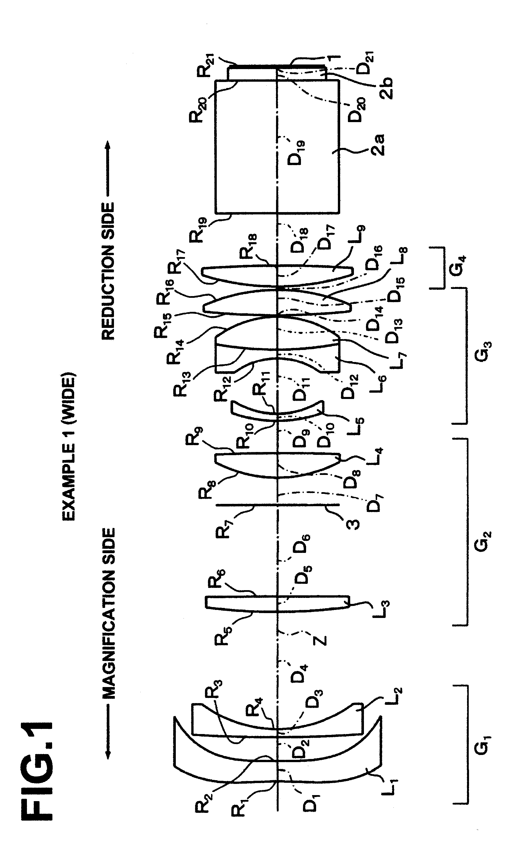
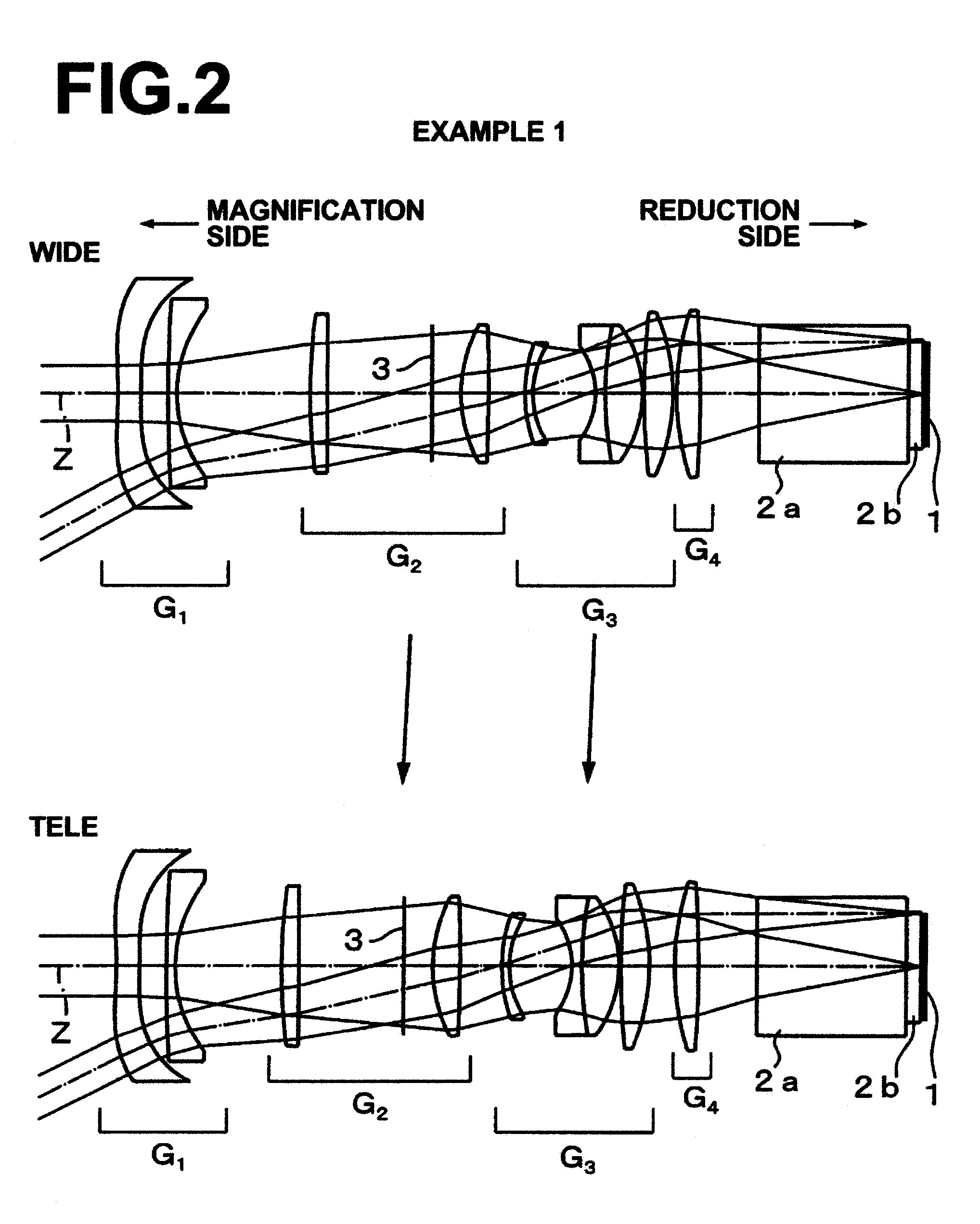
[0157]As described already, a zoom lens for projection in Example 1 is structured as illustrated in FIG. 1. Further, the path of movement of each movable lens group during zooming is illustrated in FIG. 2.

[0158]Specifically, in the zoom lens for projection of Example 1, lens groups and lenses are arranged from the magnification side of the zoom lens for projection in the order mentioned below. First lens group G1 is composed of first lens L1 and second lens L2. Both surfaces of the first lens L1 are aspheric, and the first lens L1 has negative meniscus shape having a concave surface facing the magnification side of the zoom lens for projection in the vicinity of optical axis Z. The second lens L2 is a negative meniscus lens having a concave surface facing the reduction side of the zoom lens for projection in the vicinity of the optical axis Z. Further, the second lens group G2 is composed of third lens L3, a mask 3, and fourth lens L4. The third lens L3 is a positive meniscus lens h...

example 2

[0167]A zoom lens for projection in Example 2 is structured as illustrated in FIG. 3. Further, the path of movement of each movable lens group during zooming is illustrated in FIG. 4.

[0168]The zoom lens for projection in Example 2 is structured in a substantially similar manner to the zoom lens for projection in Example 1. However, the zoom lens for projection in Example 2 mainly differs from the zoom lens for projection in Example 1 in that both surfaces of the first lens L1 are aspheric as in Example 1 but the first lens L1 in Example 2 has double concave shape on optical axis Z, and that the third lens L3 is a double convex lens, and that the ninth lens L9 is a positive meniscus lens having a convex surface facing the magnification side.

[0169]The upper section of Table 2 shows curvature radius R of each lens surface, center thickness D of each lens and air space D between lenses, effective diameter, and refractive index Nd and Abbe number νd of each lens for d-line in Example 2.

[...

example 3

[0175]A zoom lens for projection in Example 3 is structured as illustrated in FIG. 5. Further, the path of movement of each movable lens group during zooming is illustrated in FIG. 6.

[0176]The zoom lens for projection in Example 3 is structured in a substantially similar manner to the zoom lens for projection in Example 1. However, the zoom lens for projection in Example 3 mainly differs from the zoom lens for projection in Example 1 in that both surfaces of the first lens L1 are aspheric as in Example 1, but the first lens L1 in Example 3 has double concave shape on optical axis Z, and that a stop 3 is not provided within the lens system.

[0177]The upper section of Table 3 shows curvature radius R of each lens surface, center thickness D of each lens and air space D between lenses, effective diameter, and refractive index Nd and Abbe number νd of each lens for d-line in Example 3.

[0178]The middle section of Table 3 shows constants K and A3 through A10, which are aspheric coefficient...


PUM


Abstract

A zoom lens for projection includes a negative first lens group, a positive second lens group, a positive third lens group, and a positive fourth lens group, which are arranged from the magnification side of the zoom lens in the order mentioned above. The first lens group and the fourth lens group are fixed during zooming, but the second lens group and the third lens group move on optical axis Z of the zoom lens toward the magnification side, based on an operation for operating the zoom lens from wide end to tele end, in such a manner that a distance between the second lens group and the third lens group changes. Further, the following formula (1) is satisfied:
17<FG3/fw  (1), where
    • FG3 focal length of the third lens group, and
    • fw: focal length of entire system at wide end.

Description

BACKGROUND OF THE INVENTION[0001]1. Field of the Invention[0002]The present invention relates to a zoom lens for projection used as a projection lens of a projector apparatus or the like. Particularly, the present invention relates to a zoom lens for projection appropriate for a so-called front-type projector apparatus, which magnifies and projects an original image displayed on a light valve, such as a liquid crystal display device, onto a screen, and to a projection-type display apparatus on which the zoom lens for projection is mounted.[0003]2. Description of the Related Art[0004]A so-called front-projection-type projector apparatus, which projects images onto a screen in front of the apparatus, is becoming generally used for school education, company training, presentation, and the like. Further, as the market of projectors matured, the variety of projectors increased, and various projectors, such as a large projector for a large theater screen and a very small projector for a m...

Claims


Application Information

Patent Timeline
IPC IPC(8): G02B15/14
CPCG02B15/177G03B21/53G03B21/14G03B21/142G03B21/006G02B15/144515
Inventor SADO, KENZO
Owner FUJIFILM CORP
Why Eureka
Try Eureka