
Systems and Methods for Contouring a Set of Medical Images

a technology of contouring and medical images, applied in the field of contouring medical images, can solve problems such as laborious processes

Active Publication Date: 2011-11-03
MIM SOFTWARE
View PDF5 Cites 31 Cited by
  • Summary
  • Abstract
  • Description
  • Claims
  • Application Information

AI Technical Summary

Benefits of technology

[0003]Three-dimensional scans, such as CT and PET scans, produce a series of two-dimensional (2D) image slices that together make up the 3D image. Contouring these types of 3D images typically requires individually contouring each of the 2D images slices, which can be a laborious process. There is therefore a need for improved automation techniques for contouring 2D images slices to generate a 3D contour.
[0004]In accordance with the teachings described herein, systems and methods are provided for contouring a set of medical images. An example system may include an image database, an image deformation engine and a contour transformation engine. The image database may be used to store a set of medical images. The image deformation engine may be configured to receive a source image and a target image from the set of medical images in the image database, and further configured to use a deformation algorithm with the source image and the target image to generate deformation field data that is indicative of changes between one or more objects from the source image to the target image. The contour transformation engine may be configured to receive source contour data that identifies the one or more objects within the source image, and further configured to use the deformation field data and the source contour data to automatically generate target contour data that identifies the one or more objects within the target image. The image deformation engine and the contour transformation engine may comprise software instructions stored in one or more memory devices and executable by one or more processors.
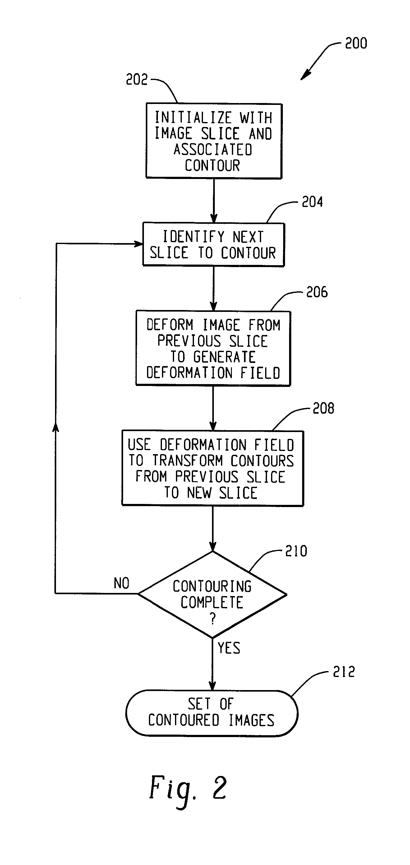
[0005]An example method of contouring a set of medical images may include the following steps: receiving a source image from the set of medical images and source contour data associated with the source image, the source contour data identifying one or more objects within the source image; receiving instructions identifying a target image in the set of medical images to contour; using a deformation algorithm to generate deformation field data from the source image and the target image, the deformation field data indicative of changes between the one or more objects from the source image to the target image; and using the deformation field data and the source contour data to generate automatic target contour data, the automatic target contour data identifying the one or more objects within the target image.
[0006]An example method for optimizing one or more parameters in a deformation algorithm may include determining a contour accuracy metric that estimates a percentage of a target contour that is likely to be manually edited. The percentage may be calculated using statistical data generated from a training set of contours. The statistical data may include a probability density function that is generated as a function of the training set of contours. The statistical data may further include a histogram of distances between a candidate contour and a reference contour in the training set of contours. The contour accuracy metric may be generated by taking a dot product of the probability density function with the histogram.

Problems solved by technology

Contouring these types of 3D images typically requires individually contouring each of the 2D images slices, which can be a laborious process.

Method used


Image

  • Systems and Methods for Contouring a Set of Medical Images
  • Systems and Methods for Contouring a Set of Medical Images
  • Systems and Methods for Contouring a Set of Medical Images

Examples


Embodiment Construction

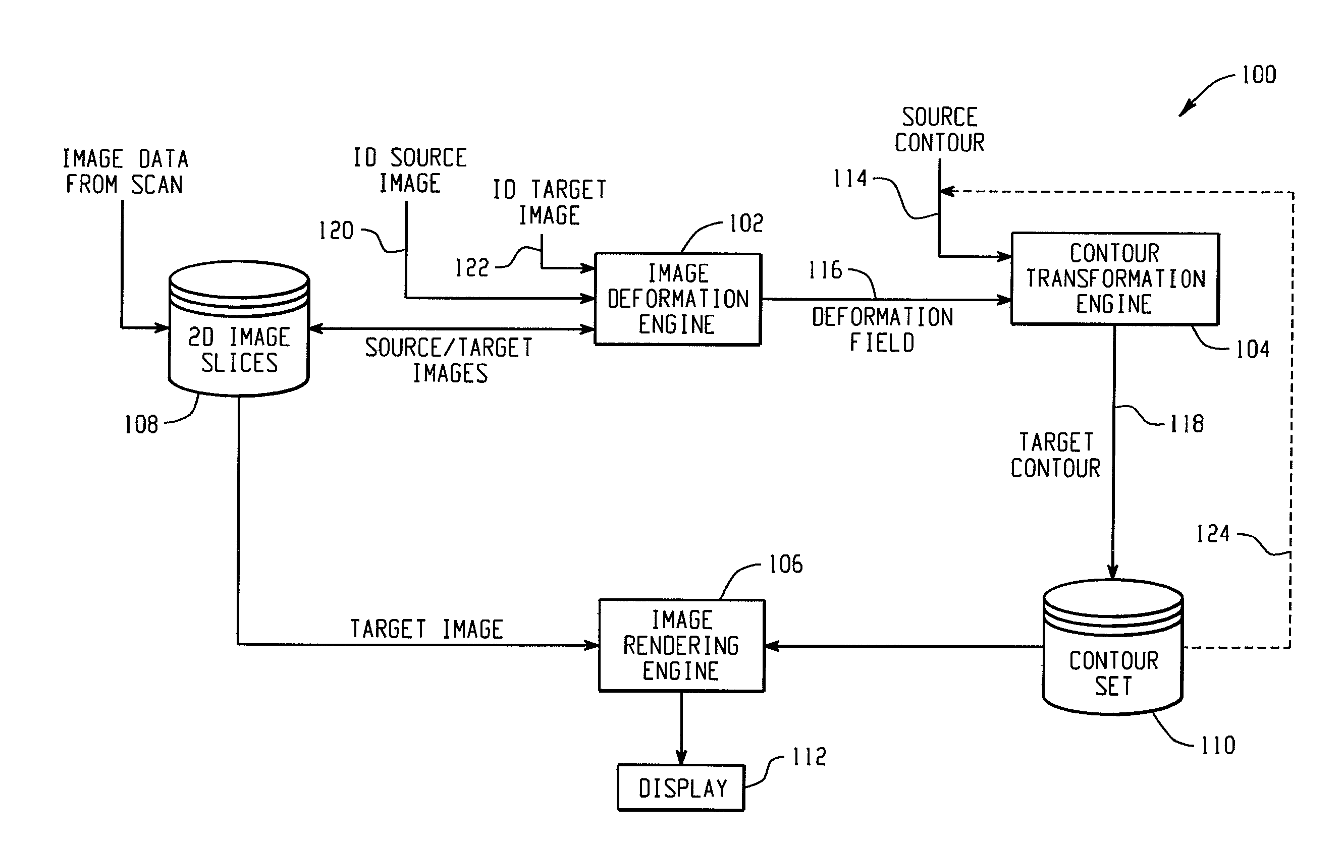
[0012]FIG. 1 depicts a block diagram of an example system 100 for contouring a set of medical images. The system 100 includes an image deformation engine 102, a contour transformation engine 104 and an image rendering engine 106. Also included in the example system 100 are an image database 108 for storing a set of two-dimensional image slices, a contour database 110 for storing contour data and a display 112. It should be understood that the image deformation engine, contour transformation engine and image rendering engine, as described herein, may be implemented by software instructions executing on one or more processing devices. In other implementations, however, one or more operations of these software engines may instead be performed by other known mechanisms such as firmware or even appropriately designed hardware. The image database and contour database, as described herein, may be implemented using one or more memory devices. For instance, in one example the image database ...


PUM


Abstract

In accordance with the teachings described herein, systems and methods are provided for contouring a set of medical images. An example system may include an image database, an image deformation engine and a contour transformation engine. The image database may be used to store a set of medical images. The image deformation engine may be configured to receive a source image and a target image from the set of medical images in the image database, and further configured to use a deformation algorithm with the source image and the target image to generate deformation field data that is indicative of changes between one or more objects from the source image to the target image. The contour transformation engine may be configured to receive source contour data that identifies the one or more objects within the source image, and further configured to use the deformation field data and the source contour data to generate automatic target contour data that identifies the one or more objects within the target image. The image deformation engine and the contour transformation engine may comprise software instructions stored in one or more memory devices and executable by one or more processors.

Description

FIELD[0001]The technology described in this patent document relates generally to the field of contouring medical images.BACKGROUND AND SUMMARY[0002]Contouring is the process of identifying an object within an image by outlining or otherwise distinguishing the object from the rest of the image. Medical images, such CT (computed tomography), MR (magnetic resonance), US (ultrasound), or PET (positron emission tomography) scans, are regularly contoured to identify certain pieces of anatomy within the image. For example, a radiologist or oncologist may contour a medical image to identify a tumor within the image. Software tools are available to assist in this type of “manual” contouring, in which the physician uses the software to create the contour by tracing the boundary of the object or objects within the image.[0003]Three-dimensional scans, such as CT and PET scans, produce a series of two-dimensional (2D) image slices that together make up the 3D image. Contouring these types of 3D ...

Claims


Application Information

Patent Timeline
Patent Type & Authority Applications(United States)
IPC IPC(8): G06K9/00
CPCG06K9/6207G06T7/0083G06T2207/30004G06T2207/10072G06T7/0097G06T7/12G06T7/174G06V10/755
Inventor PIPER, JONATHAN WILLIAM
Owner MIM SOFTWARE
Learn More