
Blades, turbine blade assemblies, and methods of forming blades

a technology of turbine blades and blade assemblies, which is applied in the direction of crystal growth process, climate sustainability, machine/engine, etc., can solve the problems of reducing structural integrity, and affecting the performance of turbine blades. , to achieve the effect of reducing the risk of rust and corrosion, and reducing the corrosion resistan

Active Publication Date: 2011-11-03
HONEYWELL INT INC
View PDF7 Cites 17 Cited by
  • Summary
  • Abstract
  • Description
  • Claims
  • Application Information

AI Technical Summary

Problems solved by technology

Consequently, the blades are subjected to high heat and stress loadings which, over time, may reduce their structural integrity.
However, current engine components, such as tips or parapets (also known as “tip cap”) of the blade, may not be adequately designed to withstand such temperatures over time.
In particular, the tips or parapets of the blade may not include active cooling and may become hotter than surrounding portions of the blade.

Method used


Image

  • Blades, turbine blade assemblies, and methods of forming blades
  • Blades, turbine blade assemblies, and methods of forming blades
  • Blades, turbine blade assemblies, and methods of forming blades

Examples


Embodiment Construction

[0016]The following detailed description is merely exemplary in nature and is not intended to limit the inventive subject matter or the application and uses of the inventive subject matter. Furthermore, there is no intention to be bound by any theory presented in the preceding background or the following detailed description.

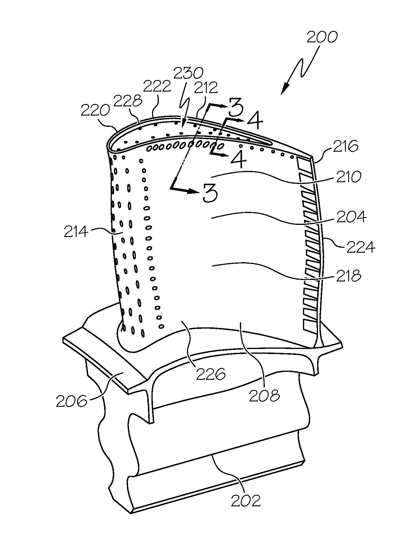
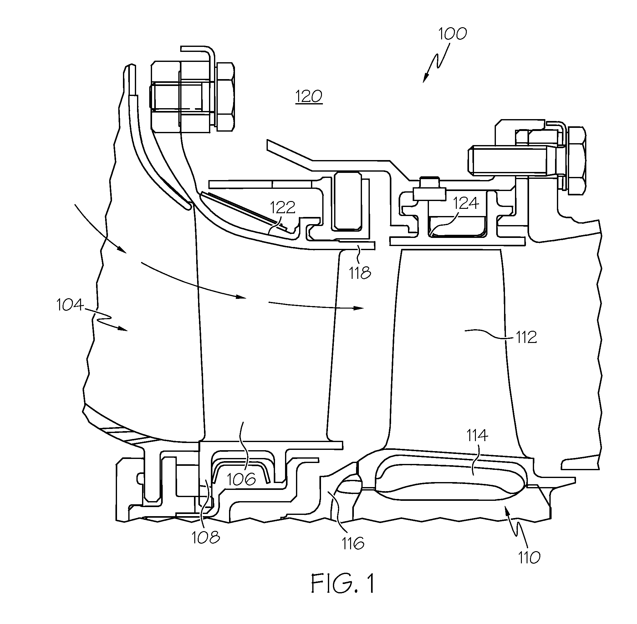
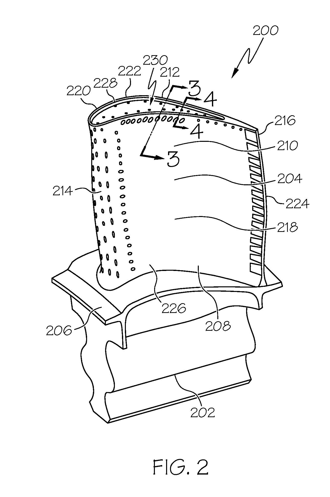
[0017]An improved blade is provided that may be implemented into components subjected to temperatures of 1150° C. or greater. The blade includes a tip to which a cladding layer may be diffusion bonded. The cladding layer is formulated to provide creep-resistance to the blade and, in this regard, may be formed from a platinum alloy. A suitable platinum alloy includes, but is not limited to, a zirconia grain stabilized platinum alloy. The improved blade may be incorporated into first stage turbine assemblies or in any other sections of an engine. Although described as being implemented a part of a turbofan gas turbine engine, the blade alternatively may be include...


PUM

PropertyMeasurementUnit
Thicknessaaaaaaaaaa
Thicknessaaaaaaaaaa
Thicknessaaaaaaaaaa

Abstract

Blades, turbine blade assemblies, and methods of forming blades are provided. The blade includes an airfoil including a convex suction side wall, a concave pressure side wall, a leading edge, a trailing edge, a root, and a tip, the convex suction side wall, the concave pressure side wall, and the tip each including interior surfaces that together define an internal cooling circuit, the airfoil including a single crystal superalloy, and a cladding layer disposed over the tip, the cladding layer including a zirconia grain stabilized platinum alloy.

Description

TECHNICAL FIELD[0001]The inventive subject matter generally relates to turbines, and more particularly relates to turbine blades and assemblies.BACKGROUND[0002]Gas turbine engines, such as turbofan gas turbine engines, may be used to power various types of vehicles and systems, such as aircraft. Typically, these engines include turbines that rotate at a high speed when blades (or airfoils) extending therefrom are impinged by high-energy compressed air. Consequently, the blades are subjected to high heat and stress loadings which, over time, may reduce their structural integrity.[0003]To improve blade structural integrity, a blade cooling scheme can be included to provide active cooling of the blade and to maintain the blade temperatures within acceptable limits. In some cases, the blade cooling scheme directs cooling air through an internal cooling circuit formed in the blade. The internal cooling circuit may include a simple channel extending through a length of the blade or may co...

Claims


Application Information

Patent Timeline
IPC IPC(8): F01D5/18
CPCC30B11/00C30B29/52F01D5/28F01D5/288F05C2201/0466F05D2300/134F05D2230/90F05D2300/143F05D2300/611F05D2300/607Y02T50/67F05D2240/307Y02T50/60
Inventor MITTENDORF, DON
Owner HONEYWELL INT INC
Learn More