Skin Retention Device for a Medical Jet Injection Kit

a technology of skin retention and injection kit, which is applied in the direction of medical devices, intravenous devices, medical devices, etc., can solve the problems of unfavorable high injection force, risk of damage, and unpredictable plasma insulin levels, so as to reduce the likelihood of the nozzle moving relative to the skin during injection and achieve a greater degree of stretching

Inactive Publication Date: 2011-11-03
NOVO NORDISK AS
View PDF8 Cites 4 Cited by
  • Summary
  • Abstract
  • Description
  • Claims
  • Application Information

AI Technical Summary

Benefits of technology

[0012]In order for the jet beam of the jet injection unit to pierce the skin of a subject, a certain strain level is required. When at first the jet beam impacts the skin surface, an elastic expansion takes place before penetration. By narrowing down the inner diameter of the adhesive covered contact face surrounding the jet beam, the elastic expansion can be minimized. This is an expected effect, but studies have shown a remarkable and surprisingly radical increase of the strain index in the thus narrowed injection zone when the inner diameter of the adhesive covered contact face is under a certain limit area. The skin is pierced when a critical strain value is reached which is reflected in the strain index. More particularly, as will be further discussed, when the inner diameter is decreased below approximately 3 mm, the strain index rises significantly more than linearly compared to the decrease and when the inner diameter is decreased below approximately 0.8 mm the strain index rises dramatically, thus creating an earlier crack in the skin for a given penetration speed and pressure. The rise in strain index is so significant that a double advantage over the known art can be achieved: a so far unknown safe and reliable jet injection is ensured, however, by a lower injection force. Hitherto it has been necessary to apply an undesirable high injection force to minimize the risk of wet shots. This has increased the risk of damage caused by intramuscular injections and the risk of altering the pharmaco-kinetics resulting in unpredictable plasma levels of insulin. But when practicing the present invention the risk of wet shots is significantly minimized yet by a lower injection force. The retaining effect achieved by the adhesive not only serves the described purpose of increasing the strain index, but also ensures that the jet beam is positioned above the initially induced opening in the skin throughout the time of the injection, an advantage especially when using a two-stage injection having a lower delivery pressure in the second stage. Further, by providing an adhesive which ensures proper contact between the nozzle and the skin, the compression at the injection site by the user forcing the nozzle too hard against the skin may be omitted, which also reduces the likelihood of injection through the subcutaneous layer and into muscle tissue. Yet another advantage of the invention is that because of the stable and secure fixation of the nozzle orifice relative to the injection opening, the duration of the second, low-pressure injection stage can be prolonged without jeopardizing injection safety. Preferably the second injection stage shall last more than 100 milliseconds, more than 1 second or even up to more than 6 seconds. This allows for the medication to slowly enter the subcutaneous layer and minimize tissue damage.
[0013]In a further aspect of the invention, the skin retention device is also adapted to stretch the skin in the proximity of the injection point. The skin stretching means are arranged circumferentially relative to the outlet nozzle, the skin stretching means having an initial first configuration corresponding to an initial state in which the skin stretching means is adapted to be placed against the skin surface of the subject, the skin stretching means being moveable to a second configuration, wherein movement of the skin stretching means to the second configuration after the skin stretching means has been placed against the skin of the subject results in the skin being stretched relatively to the outlet nozzle. By engaging and stretching the skin the likelihood that the nozzle moves relative to the skin during injection is reduced. Further, stretching of the skin will aid in keeping open the injection channel during injection (e.g. through an initially established channel during the first stage of a two-stage injection), the channel subsequently being “closed” as the stretching action is removed.
[0014]Depending on the position of the skin-engaging nozzle portion before, during, and after actuation of the skin stretching and stretching means, the skin can be stretched in different ways. For example, when the nozzle portion engages the skin at an early stage, movement of the skin stretching means between the first and second configurations may result in the skin stretching means being displaced proximally relative to the outlet nozzle, thereby stretching the skin “upwardly around” the nozzle portion. If the nozzle portion engages the skin after movement of the skin stretching means between the first and second configurations, the nozzle will engage a radially stretched skin surface. Indeed, a number of combinations are possible, for example the skin may be stretched both radially and upwards relative to the outlet nozzle.
[0015]In an exemplary embodiment the skin stretching means is arranged such that the skin is stretched circumferentially away from the outlet nozzle, i.e. similar to a drum skin. The stretching may be accomplished by a flexible skin stretching means which continuously surrounds the outlet nozzle.
[0016]When it is defined that the skin stretching means has a second configuration, this does not mean that such a second configuration necessarily is well defined, i.e. the second configuration and the degree of stretching associated therewith may depend on how the nozzle device is used by a user. For example, when the skin stretching means is forced against the skin with a given force the skin stretching means may deflect to a certain degree thereby stretching the skin, whereas the skin stretching means may deflect to a higher degree if the a larger force is applied, this resulting in a greater degree of stretching.
[0017]However, the second configuration may also be well defined, for example in case the skin stretching means has a well-defined stop-position or in case the skin stretching means is bi-stable corresponding to the first and second configurations.

Problems solved by technology

Hitherto it has been necessary to apply an undesirable high injection force to minimize the risk of wet shots.
This has increased the risk of damage caused by intramuscular injections and the risk of altering the pharmaco-kinetics resulting in unpredictable plasma levels of insulin.
Further, by providing an adhesive which ensures proper contact between the nozzle and the skin, the compression at the injection site by the user forcing the nozzle too hard against the skin may be omitted, which also reduces the likelihood of injection through the subcutaneous layer and into muscle tissue.

Method used


Image

  • Skin Retention Device for a Medical Jet Injection Kit
  • Skin Retention Device for a Medical Jet Injection Kit
  • Skin Retention Device for a Medical Jet Injection Kit

Examples


Embodiment Construction

[0037]When in the following terms as “distal”, “proximal” and “radial” or similar relative expressions are used, these only refer to the appended figures and not necessarily to an actual situation of use. The shown figures are schematic representations for which reason the configuration of the different structures as well as there relative dimensions are intended to serve illustrative purposes only.

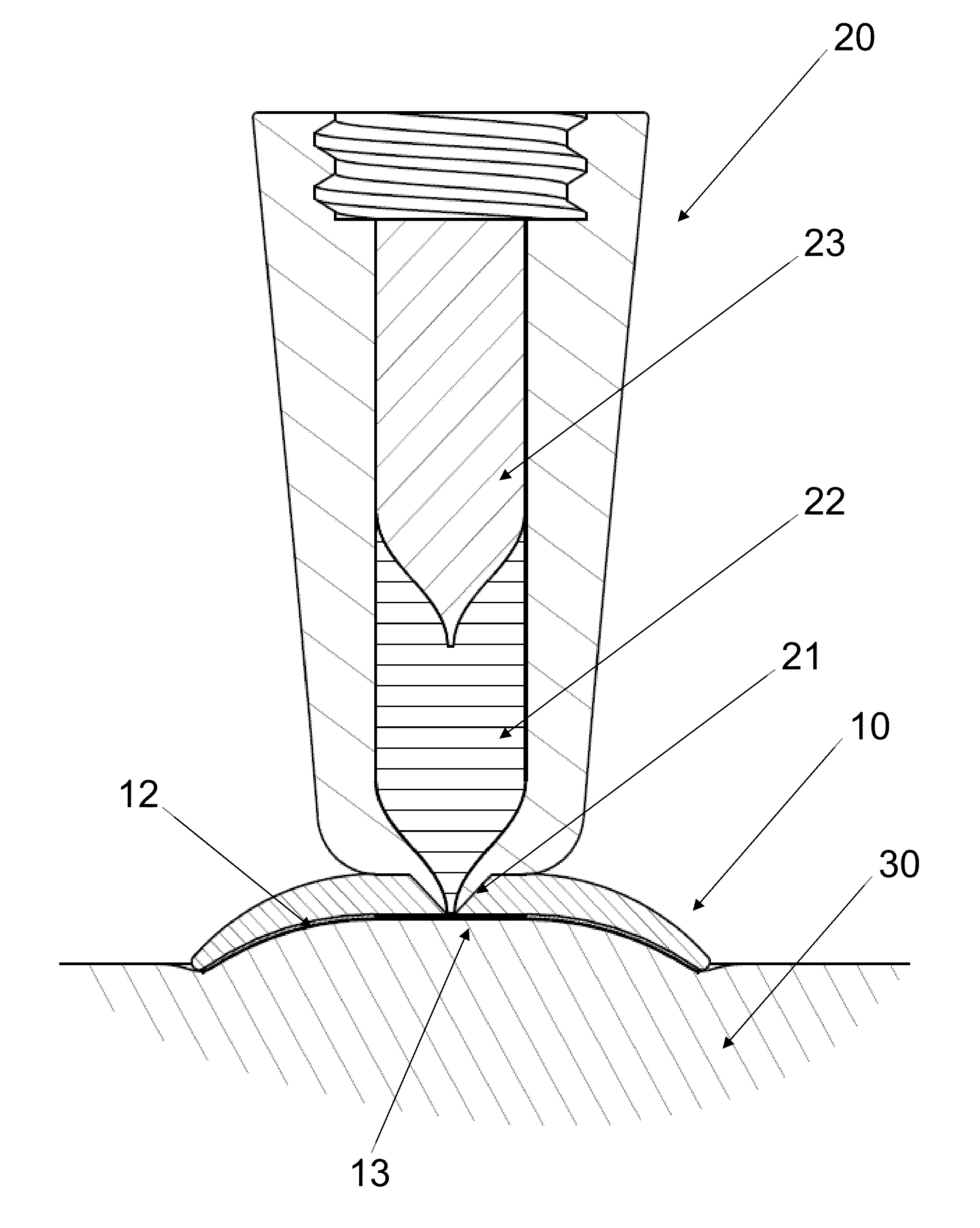
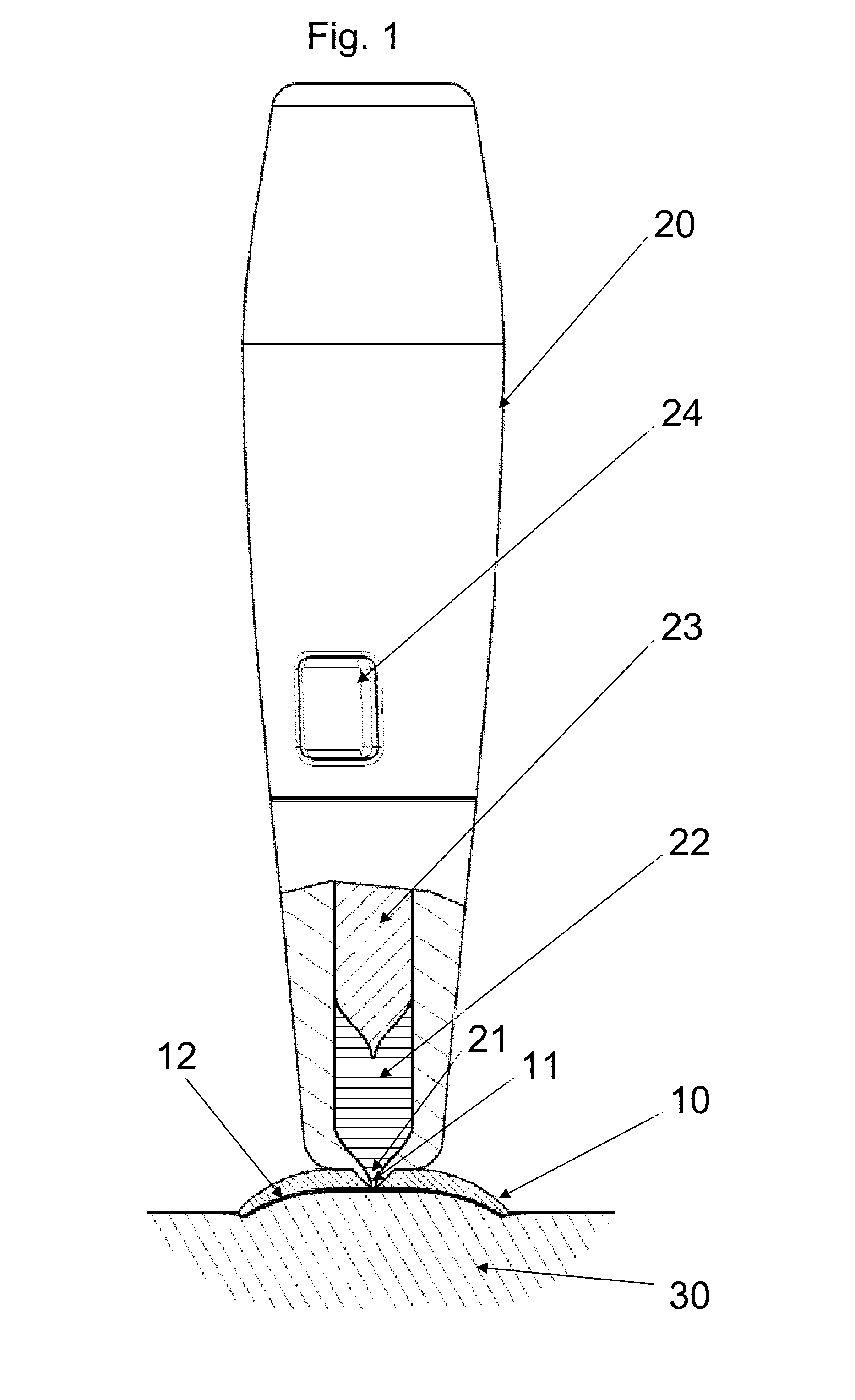
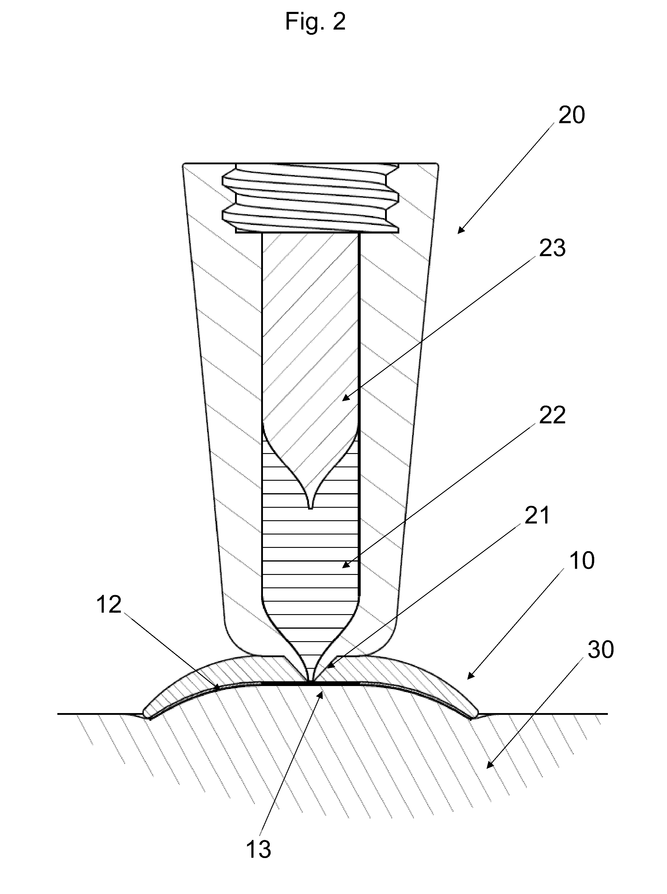
[0038]FIG. 1 shows a side view of a jet injection unit 20 and a skin retention device 10 connected thereto. The lower part of the unit is shown in sectional view to show the piston 23 slidingly arranged in a housing thereby defining a variable-volume impulse chamber 22 in flow communication with the aperture through a nozzle conduit 21. In the shown embodiment the impulse chamber is adapted for being filled with a liquid drug by suction through the nozzle conduit by moving the piston 23 proximally, however the impulse chamber unit 22 may also be provided with an opening in either the hous...


PUM


Abstract

A skin retention device 10 for a medical jet-injection unit 20 comprises a contact face provided with adhesive 12 in the area surrounding and close to the injection opening(s) 11 of the nozzle 21 which ensures god contact between the nozzle 21 and the skin 30 of a subject in the area chosen for an injection. Consequently the injection force can be lowered dramatically. In case of two-stage jet-injections, the initial injection force can be lowered because the skin retention close to the injection point significantly reduces the energy consuming elastic expansion of the skin 30 in the injection area, and the second injection force can be lowered because of the high degree of fixed positioning of the injection opening of the nozzle 21 relative to the injection channel in the skin 30 made during the initial injection stage. Thus a high degree of injection safety is achieved, minimizing the risk of whet shots, while skin lift and lower injection force decreases the risk of damage of the underlying tissue.

Description

CROSS-REFERENCE TO RELATED APPLICATIONS[0001]This application is a Divisional of U.S. application Ser. No. 12 / 158,025 filed Jun. 18, 2008 which is a 35 U.S.C. §371 national stage application of International Patent Application PCT / EP2006 / 067937 (published as WO 2007 / 071485), filed Oct. 30, 2006, which claimed priority of Danish Patent Application 05112490.7, filed Dec. 20, 2005; this application further claims priority under 35 U.S.C. §119 of U.S. Provisional Application 60 / 757,233, filed Jan. 9, 2006.[0002]The invention relates to a nozzle device adapted for placement against a skin surface of a subject, the nozzle device providing a tool for retaining and stretching the skin. The nozzle device may advantageously be used in a drug delivery device to improve interaction between the delivery device and a skin surface. For example, the nozzle device may be used in combination with an impulse generating jet injection unit.BACKGROUND OF THE INVENTION[0003]Subcutaneous and intramuscular ...

Claims


Application Information

Patent Timeline
Patent Type & Authority Applications(United States)
IPC IPC(8): A61M5/30
CPCA61M5/30A61M2005/3104A61M5/42
Inventor STROEM HANSEN, TORBENPOULSEN, JENS ULRIK
Owner NOVO NORDISK AS
Why Eureka
Try Eureka