
Battery module, electric vehicle, authentication apparatus, and discharging control method for battery module

a technology of battery modules and charging control methods, which is applied in the direction of program control, electric energy management, special data processing applications, etc., can solve the problems of high cost of large-capacity batteries, difficult to transfer battery modules b>11/b> to another appliance, and difficult for a typical household to consume all of the generated power during the day, etc., to achieve the effect of sufficient performan

Inactive Publication Date: 2011-11-03
SONY CORP
View PDF13 Cites 102 Cited by
  • Summary
  • Abstract
  • Description
  • Claims
  • Application Information

AI Technical Summary

Benefits of technology

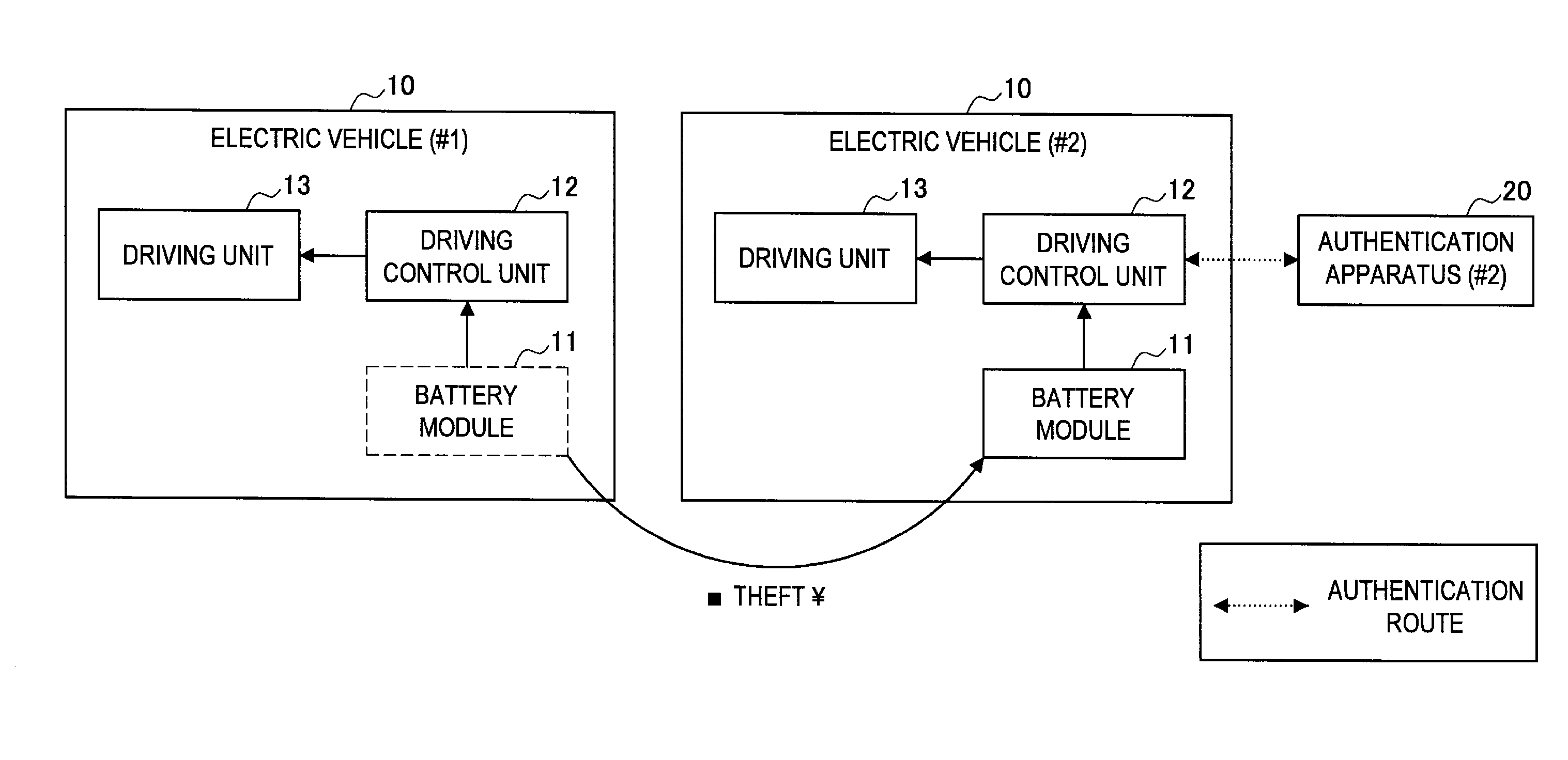
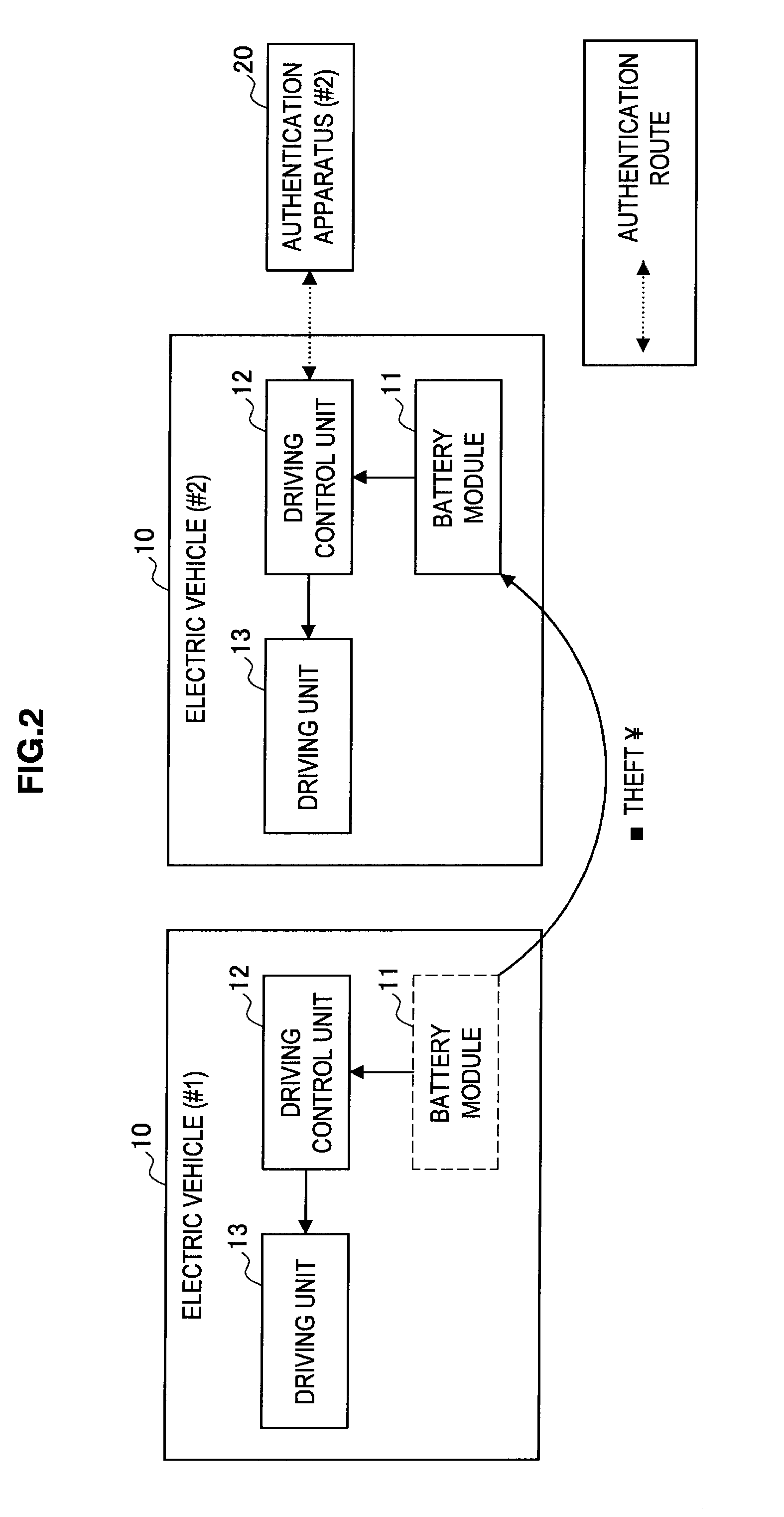
[0004]When the method disclosed in the publication mentioned above is adopted, a degree of protection against the theft of a battery provided in an electric vehicle can be achieved. However, the disclosed method does not go as far as considering a case where the battery of an electric car is transferred to another electric car or a home battery server. Since the battery of an electric car is used in a comparatively severe environment, the usage conditions are set comparatively strictly compared to a battery used in a home battery server (i.e., a home battery system) or the like. This means that in many cases, a battery that can no longer be used in an electric car can still achieve sufficient performance for use in another electric vehicle (for example, an electric bicycle or an electric motorcycle), a home battery server, or the like.
[0006]The present application was conceived in view of the problem described above and it is an aim of the present application to provide a novel and improved battery module, electric vehicle, authentication apparatus, and discharging control method for a battery module that enable a battery module to be transferred to another appliance while maintaining security against theft of the battery module.

Problems solved by technology

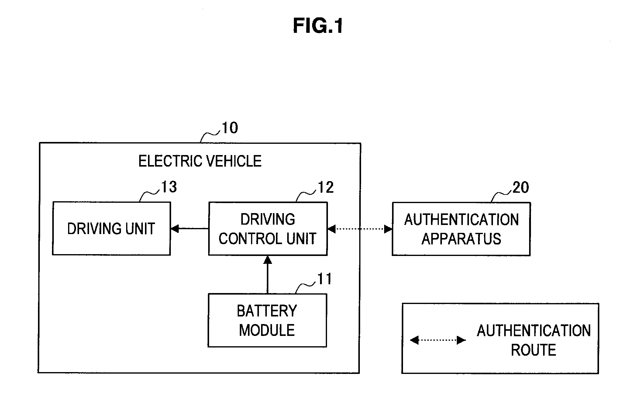
However, if electric vehicles 10 and battery modules 11 are associated on a one-to-one basis, it will become difficult to transfer the battery module 11 to another appliance, such as another electric vehicle 10 or a home battery server 30 (a home battery system).
The time zone when power is generated using such green power generating equipment does not always match a time zone when power is consumed by a household.
For example, although power is generated using photovoltaic generation equipment during the day when the sun is out, it is difficult for a typical household to consume all of the generated power during the day.
However, compact, large-capacity batteries are costly.
Meanwhile, in the case of a home battery, it is hard to imagine a severe usage situation where the output voltage changes frequently in short periods or the outputting of power in excess of a specified value is continuously maintained for a long time.
However, if electric vehicles 10 and battery modules 11 are associated on a one-to-one basis, it becomes difficult to transfer a battery module 11 to a home battery server 30 or the like.
However, with the arrangement that uses the first and second authentication mentioned above, even when a thief has moved the battery module 11 from an electric vehicle 10 to another electric vehicle 10, if the first authentication of the battery module 11 cannot be carried out successfully, the second authentication will not be implemented and it will not be possible to drive the other electric vehicle 10.
That is, the authentication method according to the present embodiment is an arrangement where it is not possible to set a bind for another transferred-to appliance unless an existing bind has been removed.
With this configuration, if the battery module 11 is stolen and connected to another transferred-to appliance, it will not be possible to use the battery module 11 at the transferred-to appliance.

Method used


Image

  • Battery module, electric vehicle, authentication apparatus, and discharging control method for battery module
  • Battery module, electric vehicle, authentication apparatus, and discharging control method for battery module
  • Battery module, electric vehicle, authentication apparatus, and discharging control method for battery module

Examples


embodiment

2. EMBODIMENT

[0066]As described earlier, there is demand for an arrangement that is capable of enabling reuse of the battery module 11 of the electric vehicle 10 while avoiding the risk of theft. The embodiment described below provides this kind of arrangement.

[0067]Overview

[0068]The arrangement according to the present embodiment includes a framework that directly authenticates the battery module 11 from outside (hereinafter referred to as “first authentication”), and when such authentication has succeeded, is capable of carrying out authentication for power on and operation of the electric vehicle 10 (hereinafter referred to as “second authentication”). For example, when the first authentication has succeeded, key information to be used in the second authentication is provided from the battery module 11 to the authentication apparatus 20. Note that the party that carries out first authentication with the battery module 11 may be the authentication apparatus 20 equipped with a func...


PUM


Abstract

There is provided a battery module including: a power storage unit storing power; a first authentication unit carrying out first authentication via a first authentication route; a second authentication unit carrying out second authentication via a second authentication route; and a discharging control unit controlling discharging from the power storage unit to an external appliance, wherein the first authentication unit is operable, when the first authentication has succeeded, to share key information to be used in the second authentication with an authentication party for the second authentication, the second authentication unit carries out the second authentication using the key information shared with the authentication party, and the discharging control unit is operable, when the second authentication has succeeded, to permit discharging from the power storage unit.

Description

CROSS REFERENCES TO RELATED APPLICATIONS[0001]The present application claims priority to Japanese Priority Patent Application JP 2010-105217 filed in the Japan Patent Office on Apr. 30, 2010, the entire content of which is hereby incorporated by reference.BACKGROUND[0002]The present application relates to a battery module, an electric vehicle, an authentication apparatus, and a discharging control method for a battery module.[0003]Increasing concern over environmental problems in recent years has led to much attention being focused on electric vehicles, starting with electric cars. As a power source, electric cars are equipped with a large-capacity battery constructed of lithium ion cells or the like. Note that the capacity of a battery provided in an electric car is around 20 kWh. When lithium ion cells are used, the cost per kWh is presently over 100,000 yen, which means that the battery provided in an electric vehicle has a high manufacturing cost. Accordingly, there is a high ri...

Claims


Application Information

Patent Timeline
Patent Type & Authority Applications(United States)
IPC IPC(8): B60L15/20H02J7/00G06F7/04
CPCB60L11/1801Y02T90/121B60L11/1838B60L11/1846B60L2200/12B60L2270/34H02J2007/0001Y02T10/7005Y02T10/7088Y02T10/7258Y02T90/128Y02T90/14Y02T90/163Y02T90/169Y04S30/14B60L11/1824Y02T10/7072B60L50/53B60L53/65H02J7/00045B60L53/305Y02T10/70Y02T10/72Y02T90/12Y02T90/167Y02T90/16B60L53/30
Inventor ISHIBASHI, YOSHIHITOTAJIMA, SHIGERUYAMAZAKI, DAISUKESUZUKI, MASAHIRO
Owner SONY CORP
Learn More