
In-situ real-time energy storage device impedance identification

Inactive Publication Date: 2011-11-03
BATTELLE ENERGY ALLIANCE LLC
View PDF5 Cites 42 Cited by
  • Summary
  • Abstract
  • Description
  • Claims
  • Application Information

AI Technical Summary

Benefits of technology

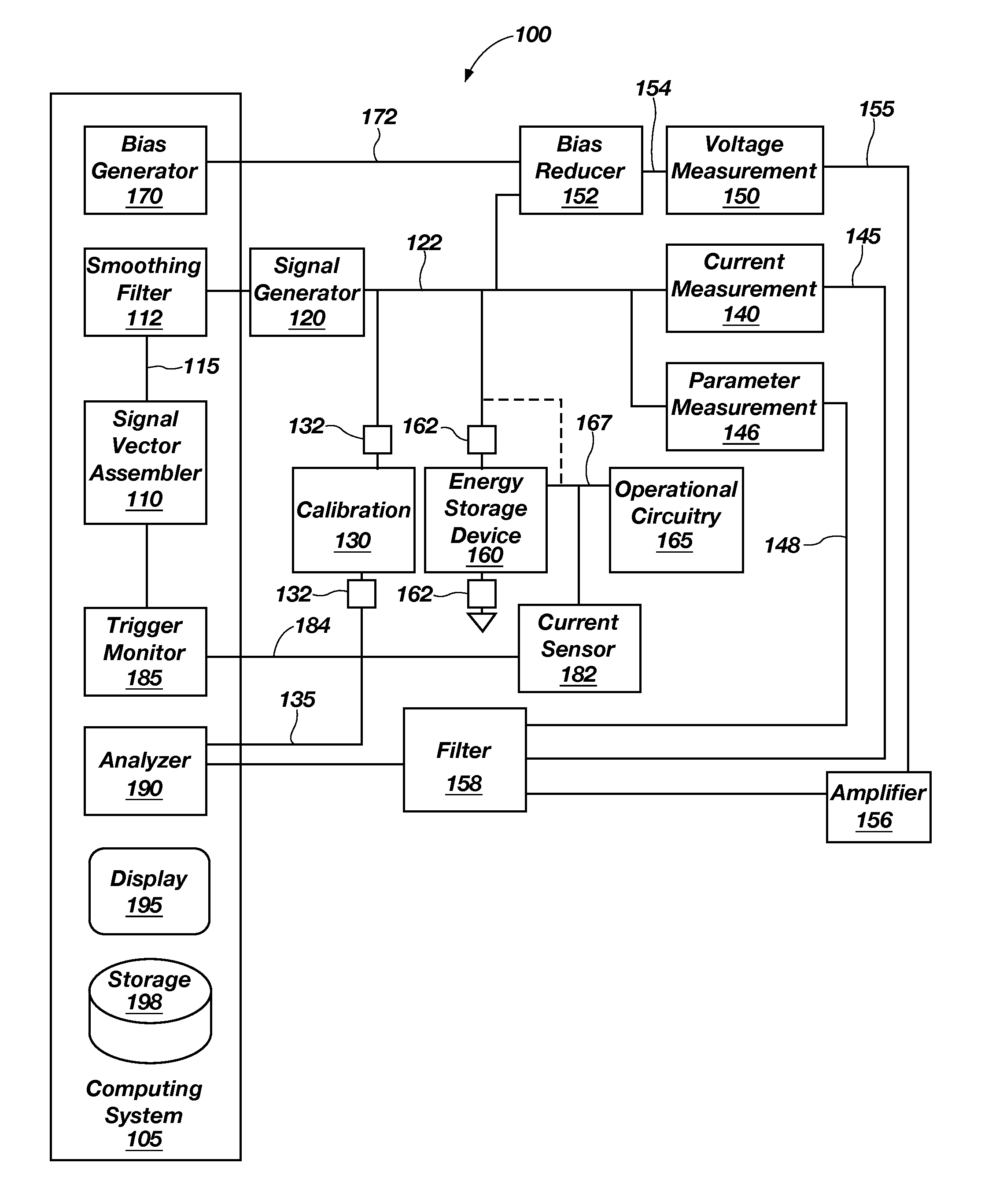
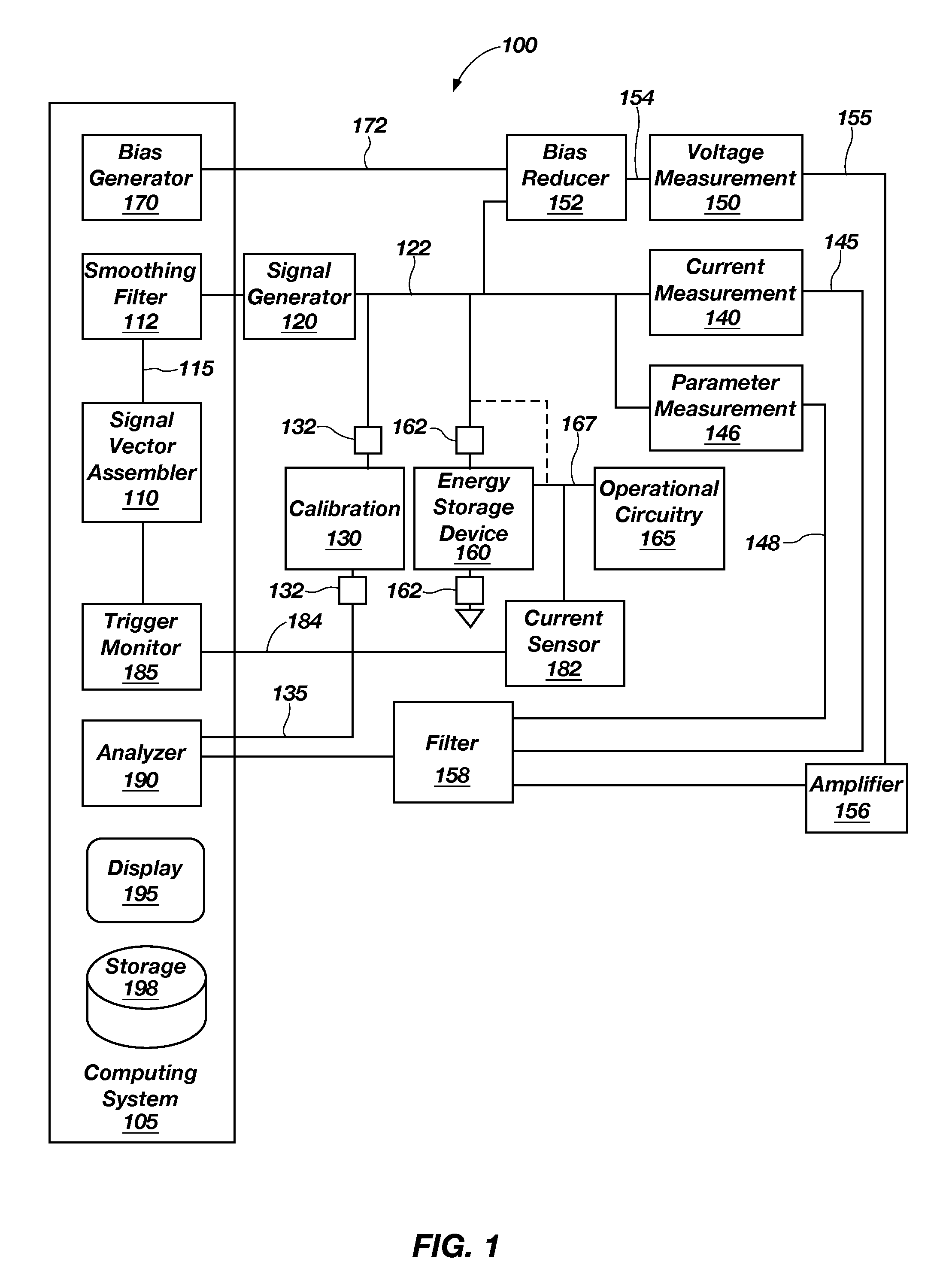
In accordance with one embodiment of the present disclosure, an impedance analysis system for characterizing an energy storage device includes a signal vector assembler configured to generate a signal vector from a composition of one or more waveforms over a stimulus duration and a signal generator configured for generating a stimulus signal responsive to the signal vector and for switchable coupling to an energy storage device. A response measurement device is operably coupled to the stimulus signal and is configured for measuring a response signal indicative of a response of the energy storage device substantially simultaneously with when the stimulus signal is applied to the energy storage device. A load variation monitor is operably coupled to the energy storage device and is configured for monitoring load variations on the energy storage device due to operational circuitry coupled thereto. An analyzer is operably coupled to the response signal and is configured for analyzing the response signal relative to the signal vector to determine an impedance of the energy storage device.
In accordance with another embodiment of the present disclosure, a method of analyzing an energy storage device includes sampling a direct current value of the energy storage device resulting from operational circuitry coupled thereto. One or more switches are closed after sampling the direct current value to operably couple an impedance analysis system to the energy storage device. A signal vector is formed for analysis of the en

Problems solved by technology

However, energy storage technologies can be very expensive, and the need for accurate state-of-health (SOH) assessment is increasing.
Though many SOH assessment techniques have been offered, no industry standard has yet been developed due to the complexity of the problem.
Simple passive monitoring of voltage, current, and temperature can yield valuable information about the remaining capacity and energy, but it yields no information about power capability.
Neither of these options are suitable for on board, in-situ SOH assessment.
The internal impedance produces power loss in a system by consuming power as a voltage drop across the source impedance.
Ideally, a perfect battery would have no source impedance and deliver any power to the extent of its stored energy, but this is not physically reasonable.
Both of these methods have limits when applied to actual conditions.
SOC determination obtained from measurement and integration of external current suffers from errors caused by internal self-discharge currents.
If the battery is not used for several days, this self-discharge current dissipates the charge within the battery and can affect the current integration approximation for battery charge.
Voltage monitoring may show errors when measurements are taken with load on the battery.
For many batteries, such as lithium-ion batteries, even after the load is removed, slow time constants and relaxation processes may continue to change the battery voltage for hours.
Also, some battery chemistries (e.g., nickel metal-hydride) exhibit a strong voltaic hysteresis, which hinders the possibility of using voltage to track capacity.
In other words, EIS may not work well when the battery is under changing loads as changes imposed upon the sine wave excitation may skew the results.
Also, the methodology of the EIS system is inherently serial (i.e., a single frequency for each step), making its application time consuming (often several hours for lower frequency sweeps) and inappropriate for a near real time analysis.

Method used


Image

  • In-situ real-time energy storage device impedance identification
  • In-situ real-time energy storage device impedance identification
  • In-situ real-time energy storage device impedance identification

Examples


Embodiment Construction

In the following description, reference is made to the accompanying drawings which form a part hereof, and in which is shown, by way of illustration, specific embodiments in which the disclosure may be practiced. The embodiments are intended to describe aspects of the disclosure in sufficient detail to enable those skilled in the art to practice the invention. Other embodiments may be utilized and changes may be made without departing from the scope of the disclosure. The following detailed description is not to be taken in a limiting sense, and the scope of the present invention is defined only by the appended claims.

Furthermore, specific implementations shown and described are only examples and should not be construed as the only way to implement the present disclosure unless specified otherwise herein. It will be readily apparent to one of ordinary skill in the art that the various embodiments of the present disclosure may be practiced by numerous other partitioning solutions.

In ...


PUM


Abstract

An impedance analysis system for characterizing an energy storage device (ESD) includes a signal vector assembler to generate a signal vector from a composition of one or more waveforms and a signal generator for generating a stimulus signal responsive to the signal vector. A signal measurement device measures a response signal indicative of a response of the ESD substantially simultaneously with when the stimulus signal is applied to the energy storage device. A load variation monitor monitors load variations on the energy storage device due to operational circuitry coupled thereto. An analyzer is operably coupled to the response signal and analyzes the response signal relative to the signal vector to determine an impedance of the energy storage device.

Description

TECHNICAL FIELDEmbodiments of the present disclosure relate generally to determining energy-output device parameters and, more specifically, to determining impedance and output characteristics of energy-storage devices.BACKGROUNDThe demand for Energy Storage Devices (ESDs) is significantly increasing as more environmentally friendly energy sources are developed and implemented in the field. The United States automotive industry, for example, is seeking to develop plug-in hybrid electric vehicle technologies that can operate a battery in charge depleting mode (i.e., all electric) for up to a 40-mile commute after 15 years of operation. However, energy storage technologies can be very expensive, and the need for accurate state-of-health (SOH) assessment is increasing. Though many SOH assessment techniques have been offered, no industry standard has yet been developed due to the complexity of the problem. Simple passive monitoring of voltage, current, and temperature can yield valuable...

Claims


Application Information

Patent Timeline
IPC IPC(8): G06F19/00G01R27/28G01R35/00
CPCG01R27/26G01R31/3679G01R31/3662G01R31/3624G01R31/3842G01R31/389G01R31/392
Inventor CHRISTOPHERSEN, JON P.MORRISON, JOHN L.MORRISON, WILLIAM H.MOTLOCH, CHESTER G.
Owner BATTELLE ENERGY ALLIANCE LLC
Learn More