Gas engine with spark plug and bore-cooling holes

a technology of gas engine and cooling hole, which is applied in the direction of spark plugs, machines/engines, mechanical equipment, etc., can solve the problems of not revealing an improvement means, causing abnormal combustion, and poor condition of the seat surface between, so as to reduce the temperature rise during the operation of the gas engin

Active Publication Date: 2011-11-10
MITSUBISHI HEAVY IND ENGINE & TURBOCHARGER LTD
View PDF12 Cites 19 Cited by
  • Summary
  • Abstract
  • Description
  • Claims
  • Application Information

AI Technical Summary

Benefits of technology

[0031]Thus, even in a case where the second check valve is arranged above and near to the pre-combustion chamber, the temperature rise during the gas engine operation can be restrained; by decreasing the maximum temperature of the second check valve in a

Problems solved by technology

Further, when the temperature level of the electrode section exceeds an allowable maximum threshold, abnormal combustion is caused in addition to the wear of the electrode section; namely, the excessive temperature causes the spontaneous combustion of the fuel gas around the electrode section at unexpected time points.
The soot deposit often causes the adhesion of the check valve toward the fitting component thereof; and, the soot deposit often causes the poor condition of the seat surface between the check valve and the bearing component thereof.
However, the structure disclosed by the patent reference 2 is limited within a system

Method used


Image

  • Gas engine with spark plug and bore-cooling holes
  • Gas engine with spark plug and bore-cooling holes
  • Gas engine with spark plug and bore-cooling holes

Examples


Embodiment Construction

[0039]Hereafter, the present invention will be described in detail with reference to the embodiments shown in the figures. However, the dimensions, materials, shape, the relative placement and so on of a component described in these embodiments shall not be construed as limiting the scope of the invention thereto, unless especially specific mention is made.

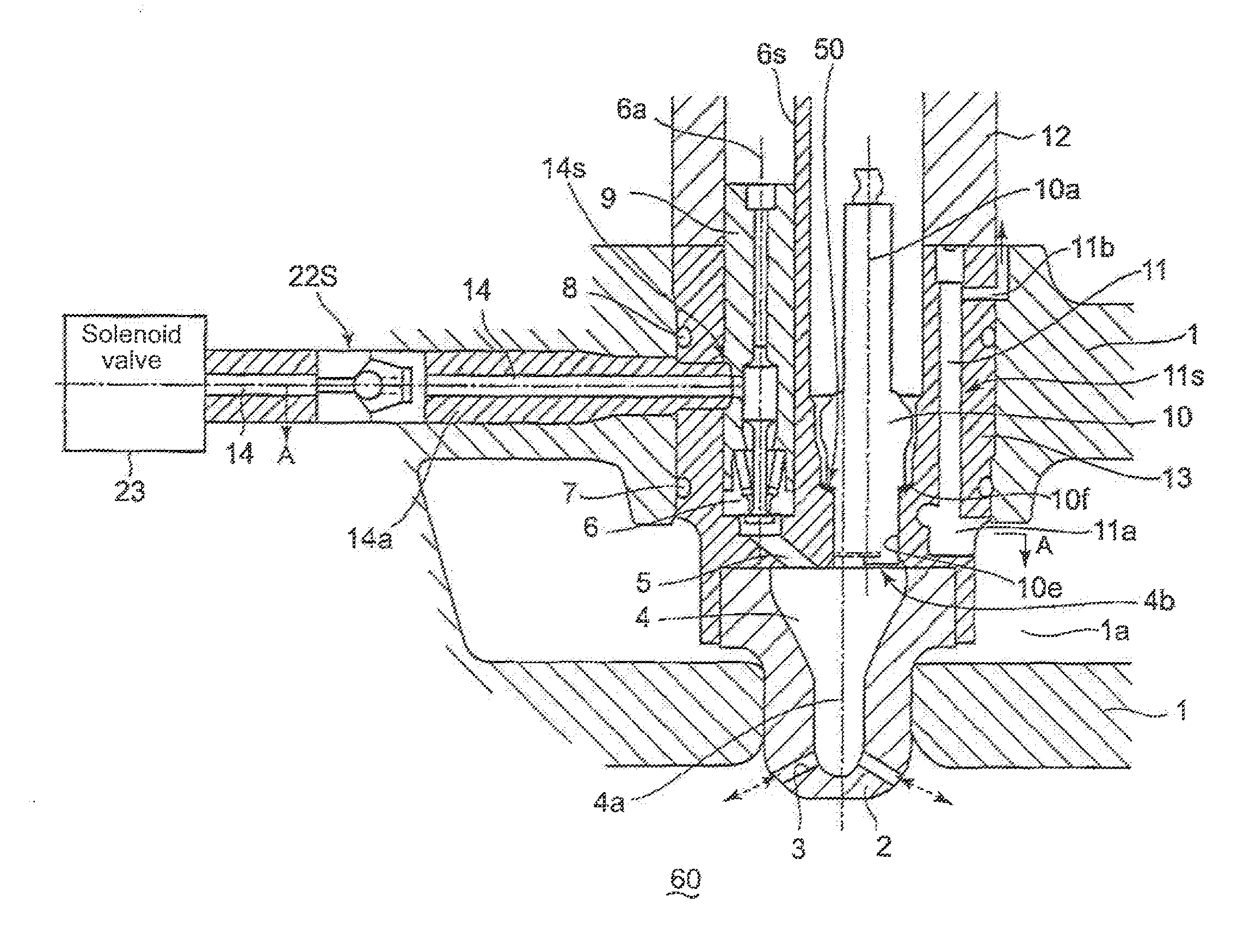
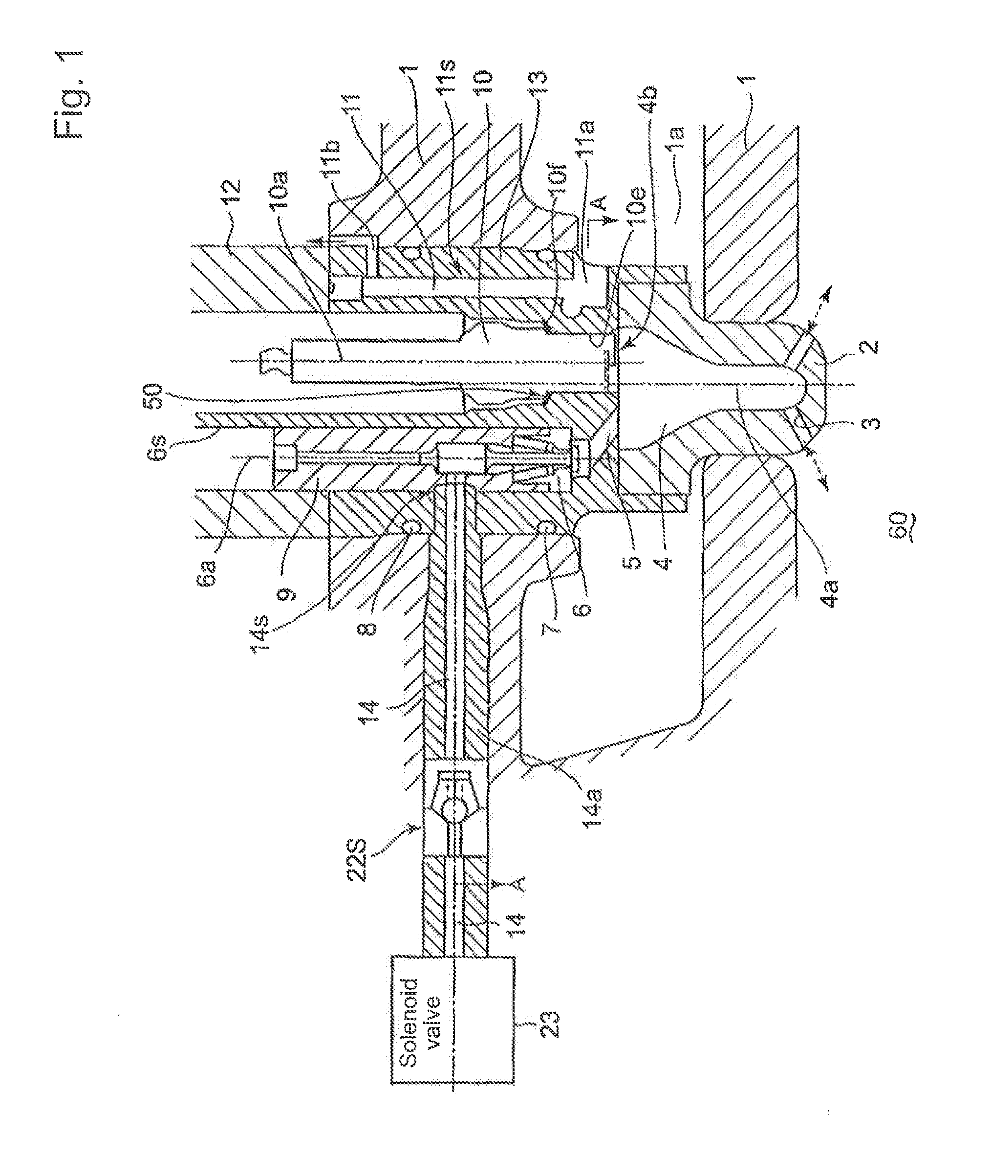
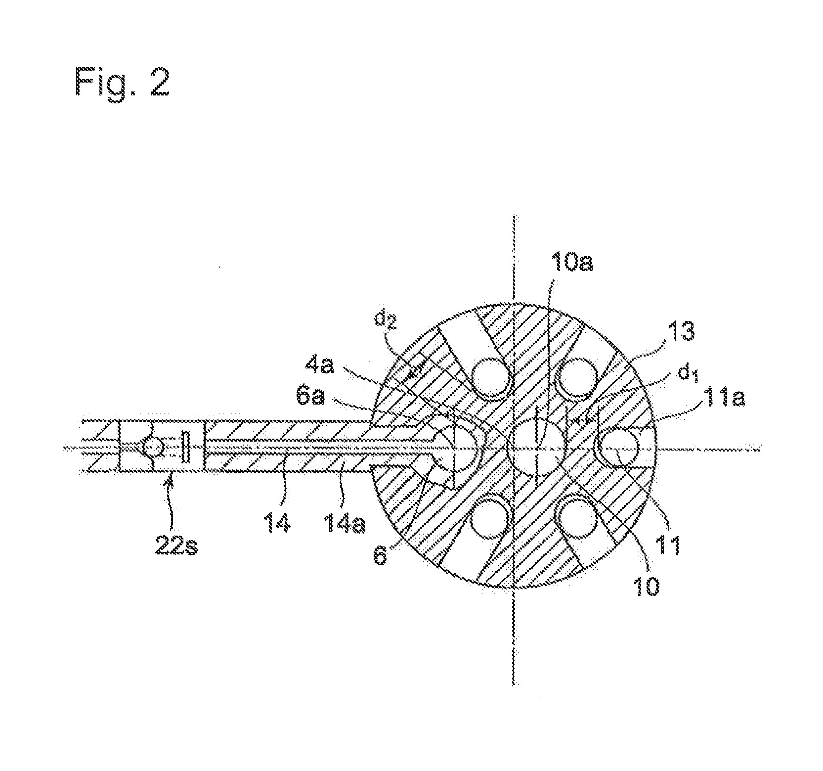
[0040]FIG. 1 is a cross-section along a center axis of an pre-combustion chamber of a gas engine provided with a spark plug, showing the pre-combustion chamber and surrounding thereof according to an embodiment of the present invention, and FIG. 2 shows A-A cross-section of FIG. 1 according to the embodiment of the present invention.

[0041]In FIG. 1, an pre-combustion chamber forming-piece 2 is fastened to a bottom wall of a cylinder head 1, the pre-combustion chamber forming-piece 2 being surrounded by a water chamber 1a, and an pre-combustion chamber 4 (4a indicates a center axis of the pre-combustion chamber) is formed, inside t...


PUM


Abstract

Provided is a check valve structure capable of preventing soot accumulation in a check valve arranged in a pre-combustion chamber (4) due to incomplete combustion of fuel gas and preventing malfunction the check valve (6) for a gas engine having an pre-combust ion chamber with a spark plug. An arrangement for supplying fuel gas to the pre-combustion chamber (4) has a multiple bore-cooling holes (11s) disposed around the spark plug (10) for cooling a gasket (10f) formed, in a mounting hardware piece (13), the holes having an lateral bore-cooling hole (11a), and a lateral bore-cooling hole (11b) with the gasket (10f) therebetween. Each of the holes further has a multiple bore-cooling holes (11s) parallel to the center axis (10a) of the spark plug. The mounting hardware piece (13) further has a check valve (6) communicating with a fuel gas inlet slot (5) between the lateral bore-cooling hole (11a)(inlet side) and the lateral bore-cooling hole (11b) (outlet side) for cooling water so that the check valve is cooled. A first check valve (22s) is provided upstream of a fuel gas inlet location (the junction) (14s) of the mounting hardware piece (13) with respect to the fuel flow to prevent reversed flow of fuel gas.

Description

BACKGROUND OF THE INVENTION[0001]1. Field of the Invention[0002]The present invention is applied to a gas engine provided with a spark plug, and relates to the gas engine provided with bore-cooling holes for cooling a circumferential space around the spark plug by use of a plurality of the bore-cooling holes.[0003]2. Background of the Invention[0004]FIG. 3 shows a cross-section around a pre-combust ion chamber 4 of a conventional gas engine provided with a spark plug, the cross-section including the vertical center axis of the pre-combustion chamber.[0005]In FIG. 3, a pre-combustion chamber forming-piece (a pre-combustion chamber mouthpiece) 2 is fastened to and on the bottom wall of a cylinder head 1, the pre-combustion chamber forming-piece being surrounded by a water chamber 1a; and, the pre-combustion chamber 4 is formed inside the pre-combustion chamber forming piece.[0006]A mounting hardware piece 13 for mounting the spark plug 13 thrusts the pre-combustion chamber forming...

Claims


Application Information

Patent Timeline
IPC IPC(8): F02B19/12
CPCF01P3/16F02B19/1014F02B19/18Y02T10/125F02P13/00H01T13/54F02F1/243Y02T10/12
Inventor ISHIDA, MICHIYASUOKUMURA, HIDEAKI
Owner MITSUBISHI HEAVY IND ENGINE & TURBOCHARGER LTD
Why Eureka
Try Eureka