Pipe member equipped with heat insulation core pipeline and u-shaped annularly-distributed pipeline

a technology of heat insulation core and pipe body, which is applied in the direction of indirect heat exchangers, lighting and heating apparatus, applications, etc., can solve the problems of thermal energy loss that occurs in the u-type piping device of u-type piping heat exchanger, and achieve the effect of preventing thermal energy loss

Active Publication Date: 2011-11-10
YANG TAI HER
View PDF10 Cites 15 Cited by
  • Summary
  • Abstract
  • Description
  • Claims
  • Application Information

AI Technical Summary

Benefits of technology

[0006]The present invention relates to a U-type pipeline capable of thermal energy transmission with each other in a radiate arrangement, wherein the piping segments of the U-type fluid piping inlet end and / or outlet end of the U-type piping capable of thermal energy transmission with each other in the radiate arrangement are directly made of thermal insulating materials, or a thermal insulating structure is installed between the inlet end and the outlet end; and the above piping system is installed within the thermal conductive body made of thermal conductive material; so as to prevent thermal energy loss because of thermal conduction by temperature difference between adjacent piping segments with temperature difference of the inlet end and the outlet end installed on the same side when fluid with temperature difference passing through.

Problems solved by technology

Traditionally, thermal energy loss often occurs in U-type piping device of U-type piping heat exchanger, because of thermal conduction by temperature difference between adjacent piping segments of fluid inlet terminal and fluid outlet terminal installed on the same side when fluid with temperature difference passing through.

Method used


Image

  • Pipe member equipped with heat insulation core pipeline and u-shaped annularly-distributed pipeline
  • Pipe member equipped with heat insulation core pipeline and u-shaped annularly-distributed pipeline
  • Pipe member equipped with heat insulation core pipeline and u-shaped annularly-distributed pipeline

Examples


Embodiment Construction

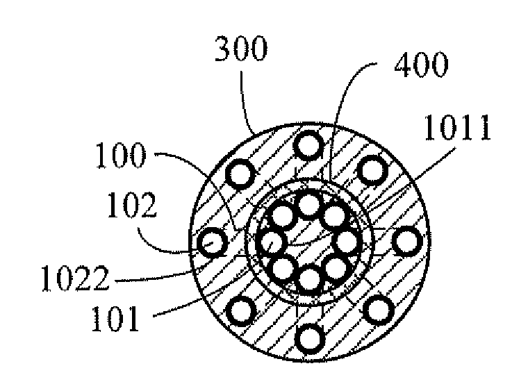
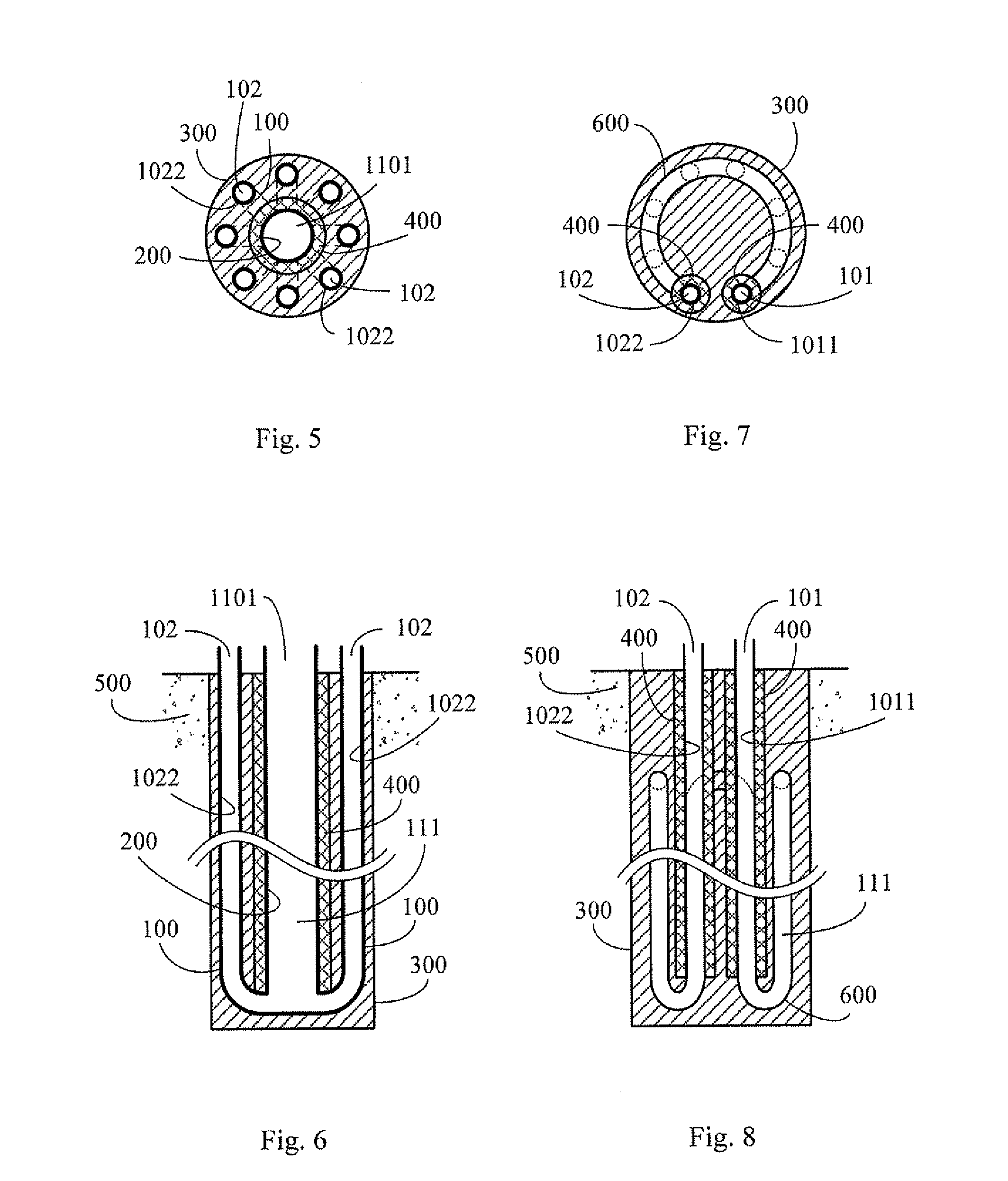
[0041]The present invention relates to a pipe member equipped with heat insulation core pipeline and U-shaped annularly-distributed pipeline for being installed within the thermal storage body (500) composed of natural thermal storage body, such as shallow surface of the earth, or pool, lake, river, ocean, or artificial objects in solid, or gaseous, or liquid state; wherein the pipe member equipped with heat insulation core pipeline and U-shaped annularly-distributed pipeline is constructed through that the piping segments of fluid inlet terminal and / or outlet terminal of the U-type core piping and loop piping are directly made of thermal insulating material, or thermal insulating structure is installed between the inlet terminal and the outlet terminal; so as to prevent thermal energy loss because of thermal conduction between adjacent piping segments of inlet terminal and outlet terminal on the same side when thermal conductive fluid with temperature difference passing through.

[00...


PUM


Abstract

The present invention relates to a U-type piping capable of thermal energy transmission with each other in a radiate arrangement, wherein the piping segments of the U-type fluid piping inlet end and / or outlet end of the U-type piping capable of thermal energy transmission with each other in the radiate arrangement are directly made of thermal insulating materials, or a thermal insulating structure is installed between the inlet end and the outlet end, and a thermal conductive body made of thermal conductive material is further installed thereof, so as to prevent thermal energy loss because of thermal conduction by temperature difference between adjacent piping segments with temperature difference of the inlet end and the outlet end installed on the same side when fluid with temperature difference passing through.

Description

CROSS-REFERENCE TO RELATED APPLICATION[0001]This application is a Continuation-In-Part of my patent application Ser. No. 12 / 588,779, filed on Oct. 28, 2009.BACKGROUND OF THE INVENTION[0002](a) Field of the Invention[0003]The present invention relates to a pipe member equipped with heat insulation core pipeline and U-shaped annularly-distributed pipeline for being installed within the thermal storage body (500) composed of natural thermal storage body, such as shallow surface of the earth, or pool, lake, river, ocean, or artificial objects in solid, or gaseous, or liquid state; wherein the pipe member equipped with heat insulation core pipeline and U-shaped annularly-distributed pipeline is constructed through that the piping segments of fluid inlet terminal and / or outlet terminal of the U-type core piping and loop piping are directly made of thermal insulating material, or thermal insulating structure is installed between the inlet terminal and the outlet terminal; so as to prevent ...

Claims


Application Information

Patent Timeline
Patent Type & Authority Applications(United States)
IPC IPC(8): F16L9/14
CPCF24J3/083F28D20/0052Y02E60/142F28F2013/005F28F2275/02F28F2270/00Y02E10/125F24T10/15Y02E10/10Y02E60/14
Inventor YANG, TAI-HER
Owner YANG TAI HER
Why Eureka
Try Eureka