Clutch device

a technology of clutch and clutch, which is applied in the direction of friction clutch, interengaging clutch, clutch, etc., can solve the problems of thermal deformation of the clutch ring, achieve the effect of improving the smoothness and quickness of the disconnection of the clutch, ensuring transmission, and ensuring transmission

Inactive Publication Date: 2011-11-10
OG GIKEN CO LTD
View PDF13 Cites 8 Cited by
  • Summary
  • Abstract
  • Description
  • Claims
  • Application Information

AI Technical Summary

Benefits of technology

[0023]According to the clutch device of the present invention, the half clutch state is produced by the diaphragm spring and the plate springs, so that as compared with a case where the half clutch state is produced only by the diaphragm spring, the half clutch range can be set at a wide range and hence the operability of the clutch when the clutch is connected can be improved and a shock caused by the sharp connection of the clutch can be effectively prevented. Further, since the air passages for making the inner peripheral side communicate with the outer peripheral side are formed between the intermediate ring and the pressure plate at specified intervals in the circumferential direction, when the intermediate ring and the pressure plate are rotated together with the flywheel, the air flow from the inner peripheral side to the outer peripheral side is formed in each of the air passages. Since the plate springs are fitted in the air passages, the plate springs can be effectively cooled by the air flowing in the air passages. Hence, this can prevent the plate springs from being thermally degraded by friction heat generated when the clutch is operated and can keep the half clutch range in a wide range for a long time and can effectively prevent the a shock from being caused by the sharp connection of the clutch for a long time.
[0024]Further, the intermediate ring is provided with the biasing means for always biasing the diaphragm spring to a side in which the diaphragm abuts against the intermediate ring, and the intermediate ring is moved integrally with the diaphragm spring by the biasing forces of the biasing means, so that smoothness and quickness in the disconnection of the clutch can be dramatically improved and hence a shift operation can be performed smoothly and quickly. Still further, since the shift operation can be performed smoothly and quickly, the transmission can be protected and the durability of the transmission can be improved and a quick shift operation can be reliably followed, which can contribute also to the shortening of time in a race or the like. Still further, the intermediate ring, the plate springs, and the pressure plate can be reliably moved, and when the clutch pedal is depressed, the clutch can be reliably disconnected, so that offensive vibration of judder or the like can be reliably absorbed by the elastic deformation of the plate springs, whereas when the foot is separated from the clutch pedal, the output of the engine can be reliably transmitted to the transmission.

Problems solved by technology

This presents a problem that when a clutch is connected, the clutch is connected rapidly more than expected to cause a shock.
This presents a problem that the cushion ring is thermally degraded by the friction heat generated when the clutch is operated to reduce the spring ability of the cushion ring, whereby the half clutch range is made narrow within a short time.

Method used


Image

  • Clutch device
  • Clutch device
  • Clutch device

Examples


Embodiment Construction

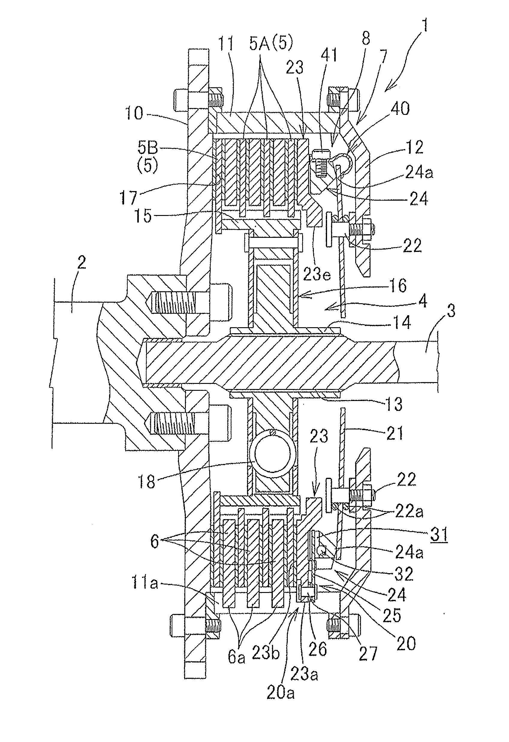
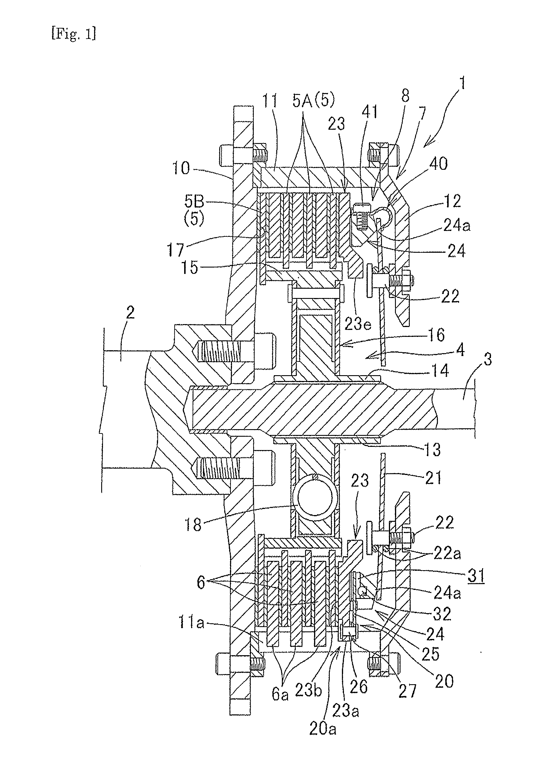
[0033]Hereinafter, an embodiment of the present invention will be described with reference to the drawings. In this embodiment, the description will be provided with a front and rear direction defined as follows: an engine side is defined as a front side and a transmission side is defined as a rear side.

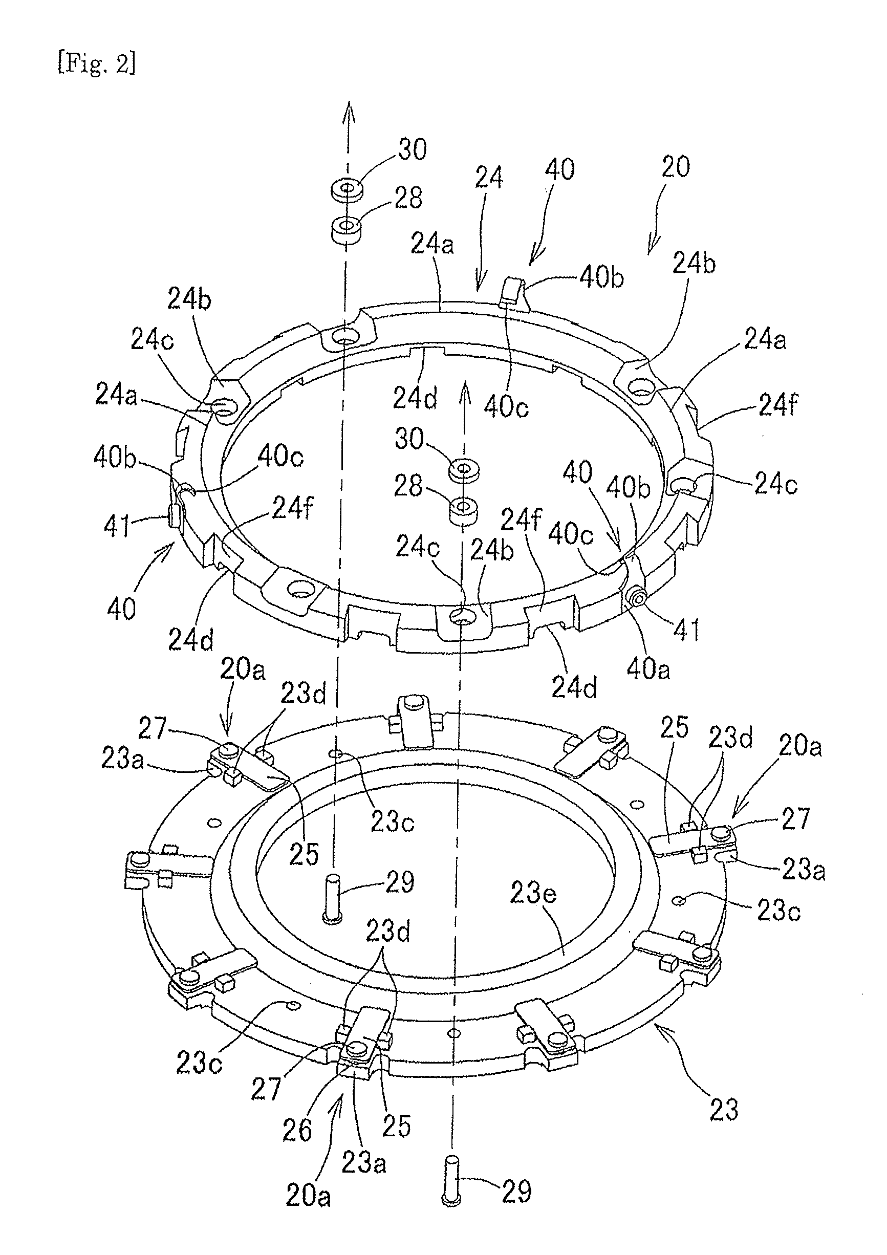
[0034]As shown in FIG. 1, a clutch device 1 is a device for connecting or disconnecting the rotational force of the crankshaft 2 to or from the input shaft 3 between a crankshaft 2 of an engine and an input shaft 3 of a transmission. The clutch device 1 is provided with: a plurality of inner clutch plates 5 fitted to the input shaft 3 via a disk support member 4 in such a way as to freely move in an axial direction and not to rotate relatively to each other; a plurality of outer clutch plates 6 each of which is arranged between adjacent inner clutch plates 5 and fitted to a clutch housing 7 rotating with the crankshaft 2 in such a way as to freely move in the axial direction and not ...


PUM


Abstract

There is provided a clutch device in which a half clutch range can be set at a wide range and in which smoothness and quickness in the disconnection of the clutch can be dramatically improved and in which a shift operation can be performed smoothly and quickly.In a clutch device 1 in which clutch plates 5, 6 are sandwiched between a flywheel 10 and a pressure plate 23 to transmit a rotational force of an engine to a transmission, the pressure plate 23 is provided with an intermediate ring 24 which can be moved freely slightly in a direction in which the intermediate ring 24 is pressed by a diaphragm spring 21, and air passages 31 for making an inner peripheral side communicate with an outer peripheral side are formed between the intermediate ring 24 and the pressure plate 23 radially at specified intervals in a circumferential direction, and plate springs 25 for always biasing the intermediate ring 24 and the pressure plate 23 in a direction in which the intermediate ring 24 and the pressure plate 23 are separated from each other are fixed in the air passages 31, and the intermediate ring 24 is provided with spring members 40 for always biasing the diaphragm spring 21 to an abutting side in which the diaphragm spring 21 abuts against the intermediate ring 24.

Description

TECHNICAL FIELD[0001]The present invention relates to a clutch device of an automobile which transmits a rotational force of an engine to a transmission and interrupts the transmission of the rotational force.BACKGROUND ART[0002]As a clutch device of an automobile has been widely employed a clutch device which includes a pressure plate rotating integrally with a flywheel, a clutch plate rotating integrally with an input shaft of a transmission, and a diaphragm spring for biasing the pressure plate to the flywheel, and in which the clutch plate is sandwiched between the flywheel and the pressure plate by a biasing force of the diaphragm spring to transmit a rotational force of an engine to the transmission, and in which an operation of pressing the pressure plate by the biasing force of the diaphragm spring is released to freely rotate the clutch plate between the flywheel and the pressure plate to interrupt the transmission of the rotational force from the engine to the transmission...

Claims


Application Information

Patent Timeline
Patent Type & Authority Applications(United States)
IPC IPC(8): F16D13/72F16D13/52F16D13/50
CPCF16D13/56F16D13/72F16D13/585
Inventor OKAZAKI, MASAHARU
Owner OG GIKEN CO LTD
Why Eureka
Try Eureka