Thermal detector, thermal detector device, and electronic instrument

Inactive Publication Date: 2011-11-10
SEIKO EPSON CORP
View PDF5 Cites 12 Cited by
  • Summary
  • Abstract
  • Description
  • Claims
  • Application Information

AI Technical Summary

Benefits of technology

[0041]As described above, the thermal detector has small structure while also having a mounting part, and the photodetector has excellent mechanical strength and high reliability. Consequently, similar effects can be provided with an electronic instrument comprising the thermal detector. Preferred examples of the electroni

Problems solved by technology

With the structure described in Japanese Laid-Open Patent Application Publication No. 2008-3081, each of the pair of horizontal beams having a prescribed length extends to both sides of the support seating, and there are thus limitations on reducing the surface area (“downsizing”) of the thermal detector unit (cell).
In addition, with the structure described in Japanese Laid-Open Patent Application Publication No. 2009-229260, a cantilevered structure is adopted in which the detector cell part is supported only by one support part, and thus problems can arise in regard to the mechanical stability of the support part.
For example

Method used


Image

  • Thermal detector, thermal detector device, and electronic instrument
  • Thermal detector, thermal detector device, and electronic instrument
  • Thermal detector, thermal detector device, and electronic instrument

Examples


first embodiment

[0055]In this embodiment, there is used a support member (membrane) that has a first arm part and a second arm part, where the first arm part is provided with a plurality of wirings (n units, where n is a natural number of 2 or greater). The second arm part, on the other hand, is provided with m wirings (where 0≦m

[0056]By utilizing this feature, the arm length of the second arm part is reduced in this embodiment. By shortening the arm length of the second arm part, the surface area occupied by the secon...

second embodiment

[0090]In this embodiment, an example will be described in regard to an arm shape that contributes to improving the degree of integration (in other words, array downsizing) in a thermal type thermal detector array in which a plurality of thermal detectors are arranged two-dimensionally. FIG. 5 is a plan view showing an example of a thermal detector having an arm shape that is suitable for a thermal detector array. In FIG. 5, the same reference symbols are used for the same parts as in the previous embodiment.

[0091]In FIG. 5, two thermal detectors 100a, 100b are arranged in the x-axis direction (first direction). The shapes of the thermal detector 100a and 100b are the same, as seen in plan view. In FIG. 5, prime marks are added to the reference symbols for the thermal detector 100b. In addition, in the example of FIG. 5, cavities 17, 17′ used for thermal isolation are provided respectively opposite the thermal detectors 100a and 100b.

[0092]In the first embodiment, the first arm part...

third embodiment

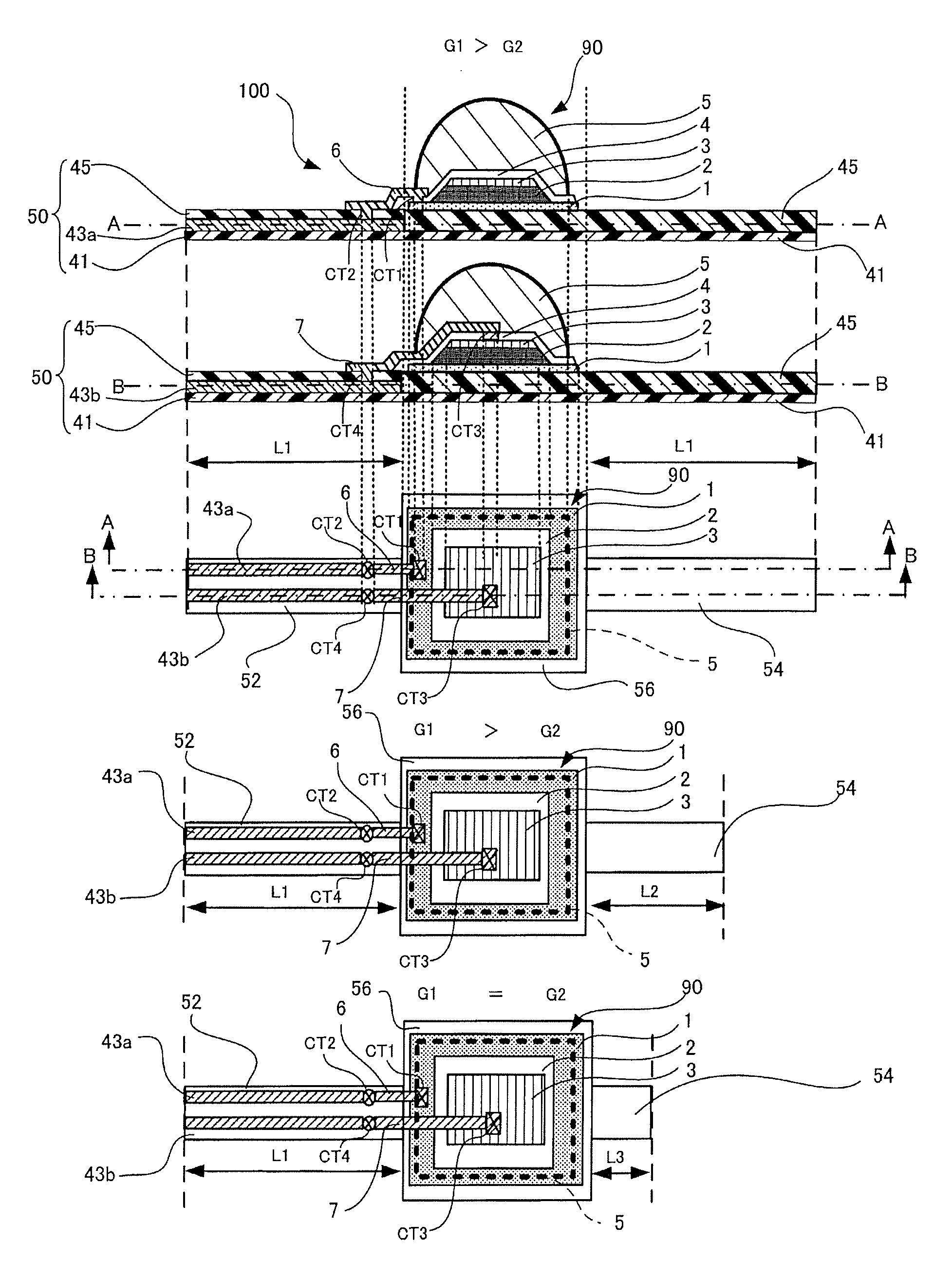
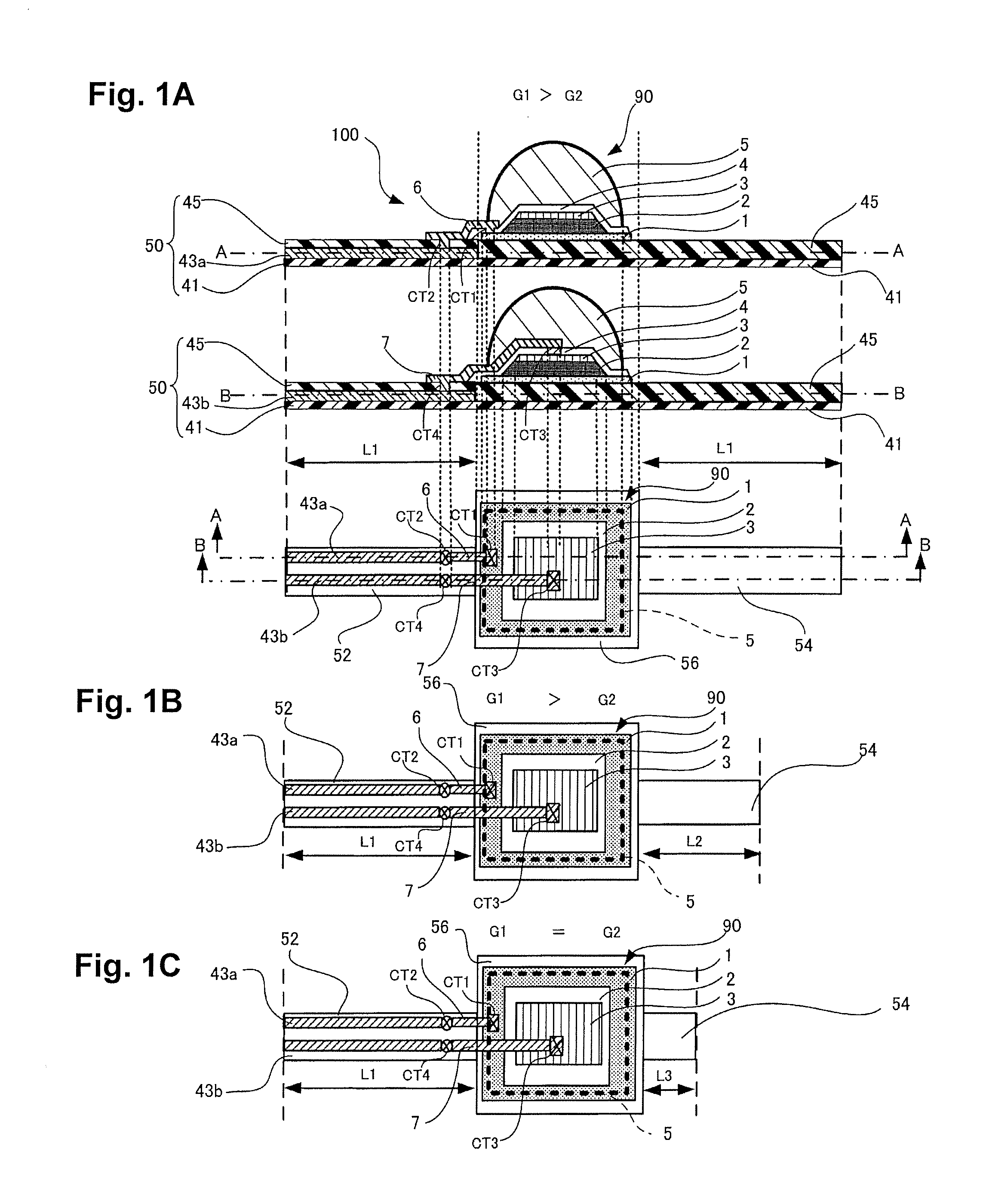
[0099]This embodiment describes another example of arm shape that will contribute to increasing the integration level (e.g., array downsizing) of a thermal detector array in which a plurality of thermal detectors are arranged two-dimensionally. FIG. 6 is a plan view showing another example of a thermal detector having an arm shape suitable for use in a thermal detector array. In the upper diagram of FIG. 6, the shape of the thermal detectors 100c and 100d is shown as seen in plan view. The middle diagram of FIG. 6 is a sectional view of the upper diagram across line A-A. The lower level of FIG. 6 is a sectional view of the upper diagram of FIG. 6 across line B-B. In FIG. 6, the same reference symbols are used for the same parts as in the previous embodiments. A prime mark is also attached to the constituent elements of the thermal detector 100d.

[0100]In the thermal detectors 100c and 100d shown in FIG. 6, the shape of the arm part as seen in plan view is the same as in the second e...


PUM


Abstract

A thermal detector has a substrate, a thermal detector element having a light-absorbing film, and a support member. The support member has a mounting part mounting the thermal detector element, a first arm part having one end that is linked to one end of the mounting part and another end that is supported on the substrate, and a second arm part having one end that is linked to the other end of the mounting part and another end that is supported on the other end of the substrate. A plurality of wirings electrically connected with the thermal detector element are provided on the first arm part, and the length of the second arm part is shorter than the length of the first arm part.

Description

CROSS-REFERENCE TO RELATED APPLICATIONS[0001]This application claims priority to Japanese Patent Application No. 2010-108370 filed on May 10, 2010. The entire disclosure of Japanese Patent Application No. 2010-108370 is hereby incorporated herein by reference.BACKGROUND[0002]1. Technical Field[0003]The present invention relates to a thermal detector, to a thermal detector device, and to an electronic instrument.[0004]2. Related Art[0005]In the field of thermal detectors, thermocouple type elements (thermopiles), pyroelectric elements, and bolometers are known. A thermopile uses thermocouples to directly detect a rise in temperature in a light absorbing film in association with absorption of light.[0006]A pyroelectric element utilizes the pyroelectric effect of a ferromagnetic body to detect a temperature rise in a light absorbing film that occurs in association with absorption of light. For example, ferroelectric PZT (lead zirconate titanate), lithium tantalate, and other such cryst...

Claims


Application Information

Patent Timeline
IPC IPC(8): G01J5/02
CPCG01J5/02G01J5/34G01J5/10G01J5/023
Inventor NODA, TAKAFUMI
Owner SEIKO EPSON CORP
Why Eureka
Try Eureka