Method of cooling a sterilizer

a sterilizer and cooling technology, applied in water installations, lavatory sanitory, construction, etc., can solve the problems of significant water consumption during this stage, and achieve the effect of considerable water consumption savings

Active Publication Date: 2011-11-10
STERIS EURO INC SUOMEN SIVULIIKE
View PDF0 Cites 3 Cited by
  • Summary
  • Abstract
  • Description
  • Claims
  • Application Information

AI Technical Summary

Benefits of technology

[0011]The filling of the jacket space with cooling water is avoided with considerable savings in terms of water consumption. Furthermore, the volume of water needed in the present cooling stage of the jacketed steam sterilizer is inherently available at the bottom of the jacket, generated as condensate of the pure steam consumed during the previous phases of the cycle. This water reservoir does not need to be replenished with fresh water for accomplishing the described cooling function.

Problems solved by technology

The water consumption during this stage is significant.

Method used


Image

  • Method of cooling a sterilizer
  • Method of cooling a sterilizer

Examples


Embodiment Construction

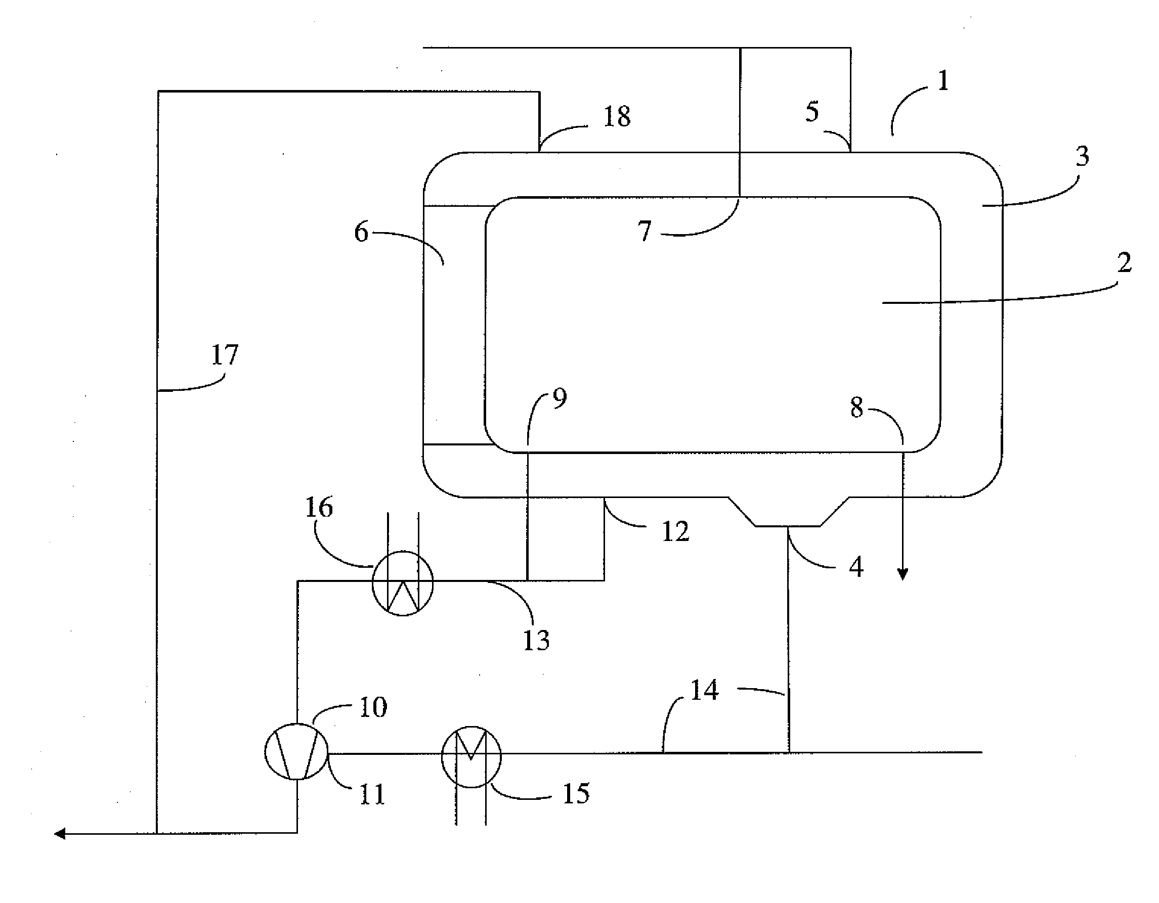
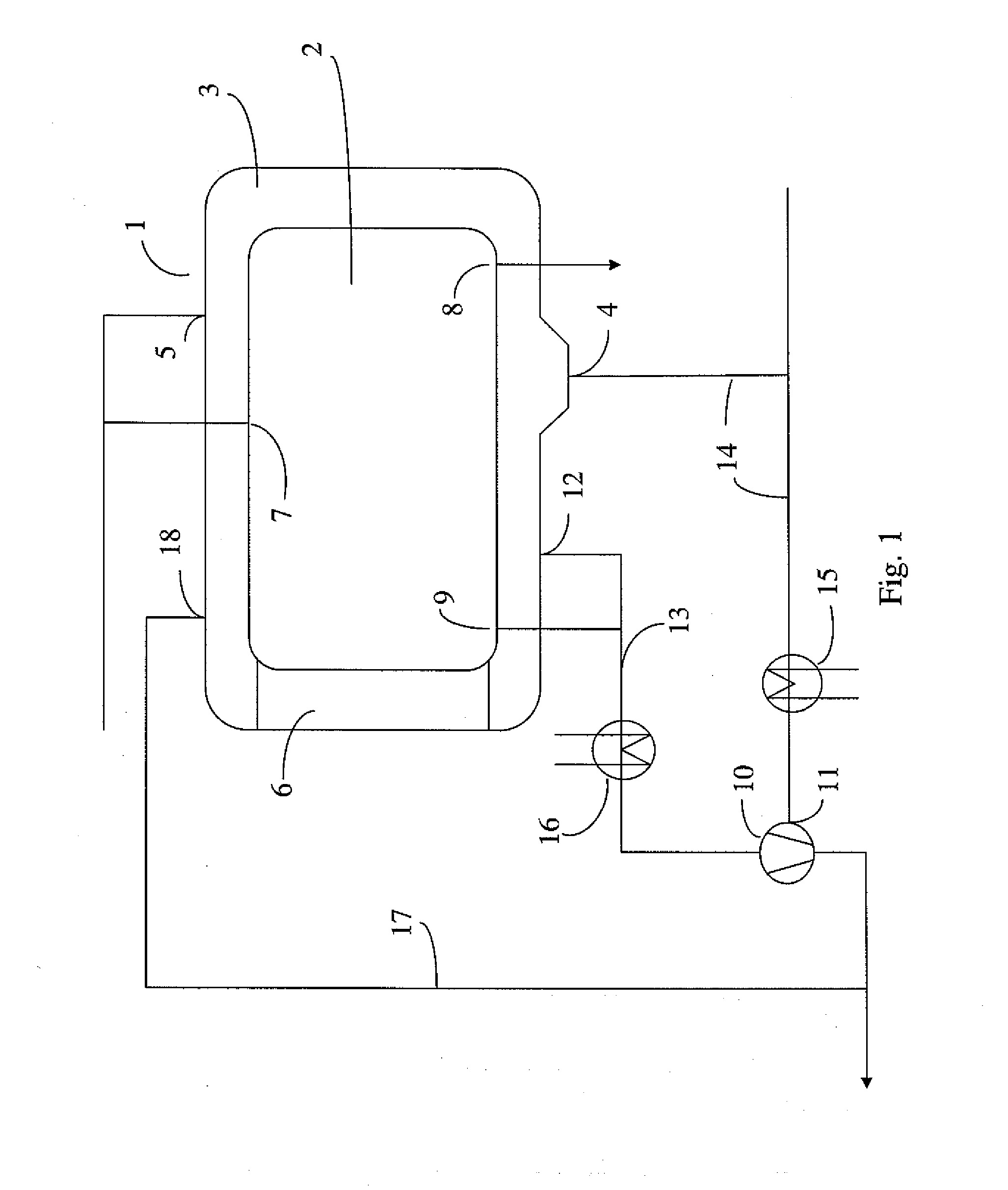
[0014]The invention will now be described in greater detail with reference to the accompanying drawing. An autoclave 1 having a chamber 2 surrounded by a jacket space 3 is shown in FIG. 1. The load of material for sterilization is charged through hatch 6. A steam inlet to the chamber is provided at 7 and a corresponding condensate outlet at 8, as well as a vacuum connection at 9. Conventionally provided lines for venting, safety valves etc. not significant for the understanding of the invention are not shown. Shut-off and control valves as conventionally provided are also not shown in the piping required for the invention.

[0015]In the context of the present invention the term jacket space 3 (or briefly jacket 3) means the space surrounding the chamber 2. The jacket space 3 is typically one space defined by jacket walls as shown in FIG. 1, but also other possible constructions are within the scope of the invention. The jacket space 3 may for example comprise interconnected spaces, se...


PUM

PropertyMeasurementUnit
pressureaaaaaaaaaa
suctionaaaaaaaaaa
temperatureaaaaaaaaaa

Abstract

Cooling of a jacketed autoclave or steam sterilizer is carried out by allowing a film of water to flow down the inner wall of the sterilizer's jacket space. Condensate from the jacket space is drawn into the water ring pump provided for vacuum in the autoclave jacket. The condensate is conducted to the water side of the pump while the normal suction line is connected at the pump to the gas zone. Thus, the water ring pump draws condensate from the lowest point of the jacket to the water side, and gas from the jacket space to the normal suction inlet. During the process of sterilizer cooling, a stream of water and air from the water ring pump is conducted to the upper part of the jacket space of the steam sterilizer and is allowed to flow as a film down the inner wall of the jacket space. Evaporation takes place with cooling of the jacket inner wall. This evaporation is enhanced by the lowering of pressure in the jacket due to the action of the water ring pump. Thus, the autoclave is cooled by a film of water flowing across the jacket inner wall while evaporating.

Description

FIELD OF THE INVENTION[0001]The invention relates to the cooling of the load of a steam-operated sterilizer. In particular, the invention relates to the efficient use of condensate for cooling.BACKGROUND OF THE INVENTION[0002]A steam autoclave for sterilizing purposes consists of a chamber with steam inlets and condensate outlets as well as other necessary connections for vacuum etc. Often a jacket is provided for temperature control, the jacket having connections for steam supply, condensate removal, vacuum and venting. An autoclave or steam sterilizer as described may go through a number of operational phases during use, like charging a load, removing the air, heating up to a temperature, exposing the load to the temperature and sterilization media, cooling and discharging the load, with several cycle variations.[0003]Heating up is carried out with steam acting directly on the load in the chamber. Prior to the heating up stage, air is removed from the chamber by pulling a vacuum i...

Claims


Application Information

Patent Timeline
Patent Type & Authority Applications(United States)
IPC IPC(8): A61L2/20F28D15/00
CPCA61L2/26A61L2/07
Inventor SALMISUO, MAURIPETTERSSON, JANI
Owner STERIS EURO INC SUOMEN SIVULIIKE
Why Eureka
Try Eureka