Improved tunnel ventilation device

a tunnel ventilation and tunnel technology, applied in the direction of pliable tubular containers, heating types, containers, etc., can solve the problems of reducing installation efficiency, reducing the efficiency of air jet fracturing, and requiring more complex control systems

Inactive Publication Date: 2011-11-10
MOSEN
View PDF7 Cites 38 Cited by
  • Summary
  • Abstract
  • Description
  • Claims
  • Application Information

AI Technical Summary

Benefits of technology

[0129]It will be appreciated that where the fan (or fans) is capable of blowing bi-directionally, the inlet flow to the fan or fans may, in principle, need to (or would, in principle, need to where the assembly has two nozzles, one for each flow direction) pass through a nozzle before entering the fan or fans. This may restrict the inlet flow to the fan or fans.
[0130]Thus, in one particularly preferred embodiment where bi-directional fan(s) are used, the fan

Problems solved by technology

A fraction of the air jet's momentum is lost due to frictional drag on tunnel surfaces, and due to form drag on any bluff bodies that the jet impinges upon.
Irreversible processes such as friction of the jet along the tunnel soffit or floor will cause a reduction in the installation efficiency, typically to a value below unity.
However, the impulse ventilation option requires the construction of fan chambers at each portal; generates high airflow velocities in the immediate vicinity of the nozzle; and may require more complex control systems, e.g. variable speed fans with inverter drives.
Instead, they are installed deep within tunnels, which drives up the cost of cabling.
The Coanda effect causes additional frictional drag, and hence a reduction in the effective thrust generated by the jet.
However, this benefit should be balanced against the larger air

Method used


Image

  • Improved tunnel ventilation device
  • Improved tunnel ventilation device
  • Improved tunnel ventilation device

Examples


first embodiment

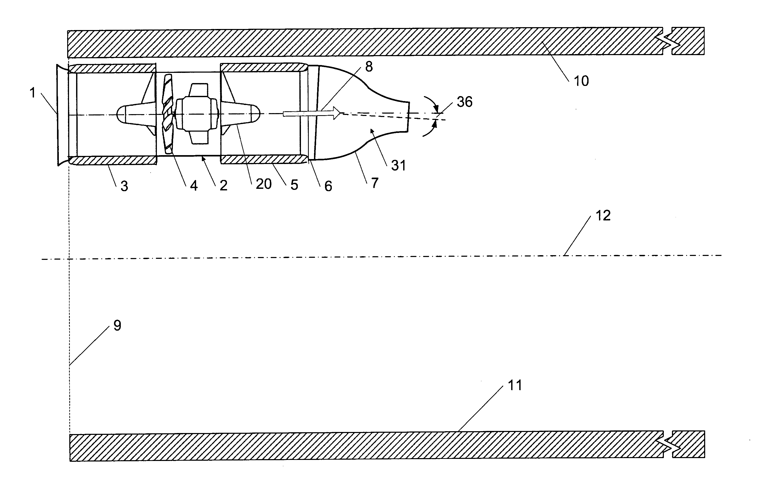
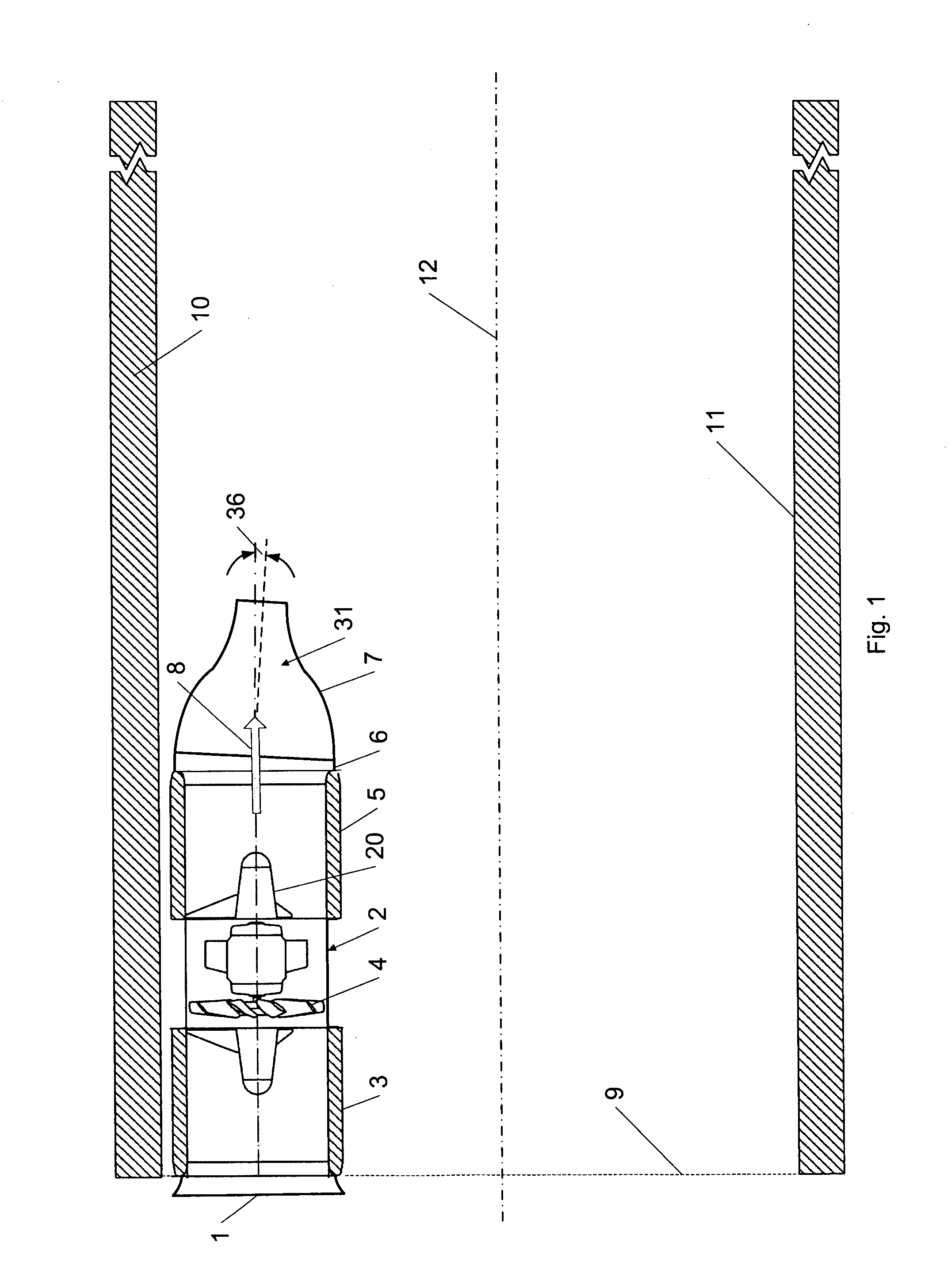
[0184]Referring to FIG. 1, this shows a side view of this invention.

[0185]In this embodiment, a fan assembly comprising a fan (2) is installed in the vicinity of a tunnel portal (9). The airflow (8) enters the fan (2) through a bellmouth transition (1) and passes through silencers upstream (3) and downstream (5) of a fan rotor (4) which is supported by a centrebody (20). The airflow is directed through the throughbore (31) of a convergent nozzle (7) (i.e. a nozzle whose throughbore decreases in cross-sectional area, in this case from its inlet to its outlet) which may be directed at a certain angle (36) towards the centreline of the tunnel (12) and away from the tunnel soffit (10) by the installation of an angled transition piece (6). The flow angle is arranged to avoid the attachment of the jet to the tunnel floor (11).

[0186]As shown and discussed above, the nozzle converges to a cross-sectional area that is less than the area of the ductwork surrounding the fan rotor at the positi...

second embodiment

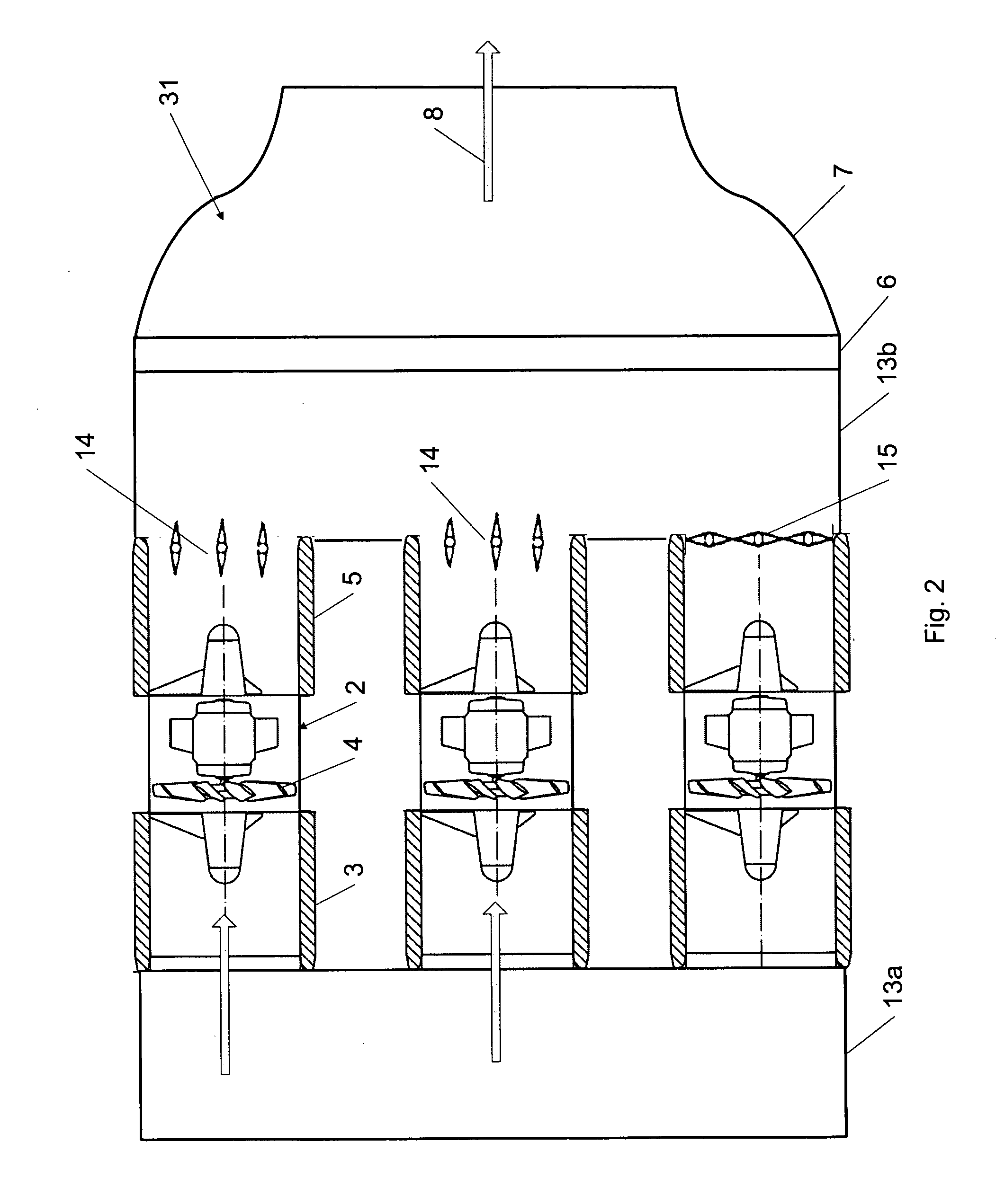
[0187]FIG. 2 presents a plan view of this invention, in which the fan assembly includes a bank of fans. This assembly may again be installed within a tunnel, in the vicinity of a portal. The airflow (8) enters the fans through a common entry plenum (13a), which serves to reduce the overall entry pressure drop to the fan assembly (ventilation device). A number of fans may not be operational due to maintenance, or serve as backup devices only, and are shut off from the airflow path using closed dampers (15). The operational fans drive the flow through open dampers (14) into a common exhaust plenum (13b). The flow is then directed through an angled transition piece (6) and into a convergent nozzle (7). It is also possible to direct the flow from the fans into multiple convergent nozzles.

[0188]Again, it should be noted here that the minimum cross-sectional area of the nozzle is less than the combined cross-sectional area of the ductwork at each fan rotor, so that the nozzle will act to ...

third embodiment

[0189]FIG. 3 presents a side view of this invention, which provides a bidirectional ventilation device that may again be installed in a tunnel. The example provided by FIG. 3 shows the airflow (8) flowing from left to right, but an opposite airflow direction from right to left is also possible through the same fan assembly. A reversible fan rotor (4) draws air through a nozzle (7) and also through open dampers (14) which allow an inlet flow that bypasses the nozzle (7). The sum of the free areas for air intake through the nozzle and the open dampers is preferably arranged to be no less than the cross-sectional area of the ducting at the fan rotor. At the discharge from the fan, closed dampers (15) direct the flow to another convergent nozzle, which discharges the air into the tunnel.

[0190]The blades in the open dampers (14) will preferably be arranged to open at certain angles, to minimise the aerodynamic pressure drop across them. Such opening angles will ensure the smooth running ...


PUM


Abstract

A ventilation device that enhances the longitudinal thrust of a fan (2) installed within a tunnel, by the introduction of a convergent nozzle (7) to accelerate the outlet flow (8). An angled transition piece (6) can turn the flow by a specific angle (36). Multiple fans can be connected to common inlet and outlet plenums, supplying one or more convergent nozzles. Bi-directional flow can be achieved by fitting convergent nozzles to both sides of a fan, with bypass dampers optionally installed between the fan and the two nozzles. The nozzle trailing edge can be shaped with multiple lobes, chevrons or tongues, and the fan centre-body can be shaped with multiple lobes. A fire suppression agent such as water mist can be supplied into the ductwork between the fan and the nozzle trailing edge. Acoustic silencing can be achieved using the absorbent material on the nozzle and fan centre-body.

Description

BACKGROUND OF THE INVENTION[0001]This invention relates to an improved tunnel ventilation device. Tunnels may require ventilation for a variety of reasons—for example to ensure an adequate air quality, to control the spread of smoke in case of fire, or to reduce temperatures to acceptable limits. The function of the ventilation relates to the type of tunnel in question—vehicular tunnels (road, rail and metro) generally require high air quality during normal operation and smoke control in case of fire, while cable tunnels require cooling, smoke control and a certain amount of air exchange. Mine tunnels and station tunnels also require adequate ventilation for physiological, cooling and smoke control requirements. A number of alternative ventilation systems are available for designers to achieve these requirements. For short and medium-length road tunnels (depending on the relevant national guidance, up to approximately 3 km in length for tunnels with unidirectional traffic), longitud...

Claims


Application Information

Patent Timeline
IPC IPC(8): E21F1/00B05B1/00
CPCA62C3/0221F04D29/547F04D29/441E21F1/003E21F1/00F04D19/00F04D29/44F04D29/54F04F5/46F24F7/007F24F13/06
Inventor TARADA, FATHI
Owner MOSEN
Why Eureka
Try Eureka