
Anchors with Biodegradable Constraints

Active Publication Date: 2011-11-10
GI DYNAMICS
View PDF5 Cites 90 Cited by
  • Summary
  • Abstract
  • Description
  • Claims
  • Application Information

AI Technical Summary

Benefits of technology

[0006]Embodiments of the present invention provide improved anchoring of an implant in the gastrointestinal tract and can increase the duration that an implant can be anchored in the intestine by providing biodegradable constraints that maintain anchoring protrusions in a constrained state until the constraint releases.
[0014]Alternatively, the protrusion can include a length of wire formed in a helix. The wire used to form the helix may be coiled to form the loop, which can be oriented such that it is parallel to the luminal wall when deployed within the lumen. (Other orientations of the loop are also possible.) The helix may have a tapered profile (e.g., a conical profile) when viewed from the side, and can be flattened alongside the collapsible anchor. The collapsed implant can be inserted into the lumen endoscopically. Releasing the helix and the anchor from the collapsed state causes the helix to push the loop away from the anchor, which, in turn, causes a face of the loop to engage the luminal wall. The implant may also include an end effect at or near the tip of the loop to aid penetration of the loop through the luminal wall.

Problems solved by technology

It also exerts an enormous strain on the body that affects the organs, the nervous system, and the circulatory systems.
Obesity rates have been rising for years in the United States, causing corresponding increases in healthcare expenditures.
Curing obesity has so far vexed the best efforts of medical science.
Dieting is not an adequate long-term solution for most obese people, especially those with a body-mass index of over 30.

Method used


Image

  • Anchors with Biodegradable Constraints
  • Anchors with Biodegradable Constraints
  • Anchors with Biodegradable Constraints

Examples


Embodiment Construction

[0030]A description of example embodiments of the invention follows.

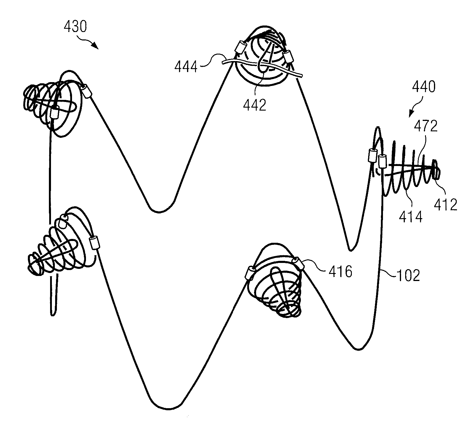
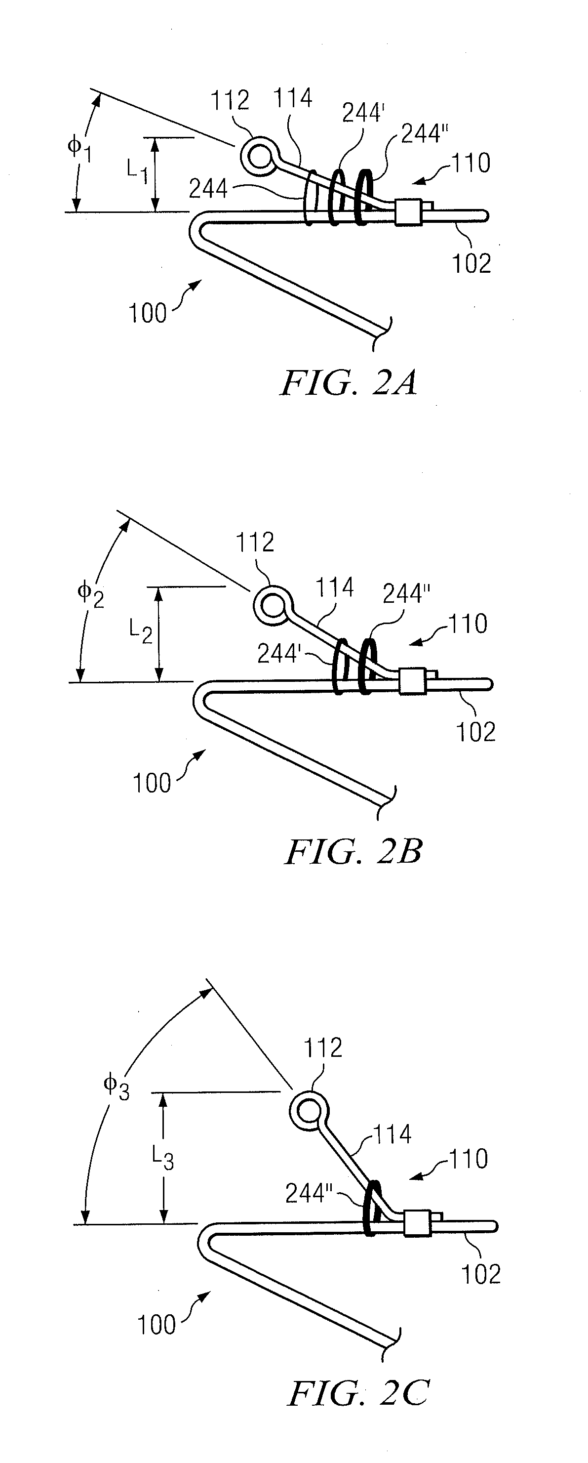
[0031]An anchor may be used to secure a sleeve in the intestine of a patient for treating obesity and / or type-2 diabetes as described in commonly assigned U.S. Pat. No. 7,025,791; U.S. Pat. No. 7,608,114; U.S. Pat. No. 7,476,256; U.S. Pat. No. 7,815,589; U.S. patent application Ser. No. 11 / 330,705, filed on Jan. 11, 2006, by Levine et al.; U.S. patent application Ser. No. 11 / 827,674 filed on Jul. 12, 2007, by Levine et al., all of which are incorporated herein by reference in their entireties.

[0032]As described in the above-referenced patents and patent applications, straight, sharp barbs fixed to a self-expanding anchor may be used to secure an implant to the duodenal wall. However, the body's healing response stimulates a progressive tissue proliferation around sharp barbs in response to the injury caused as the anchor pushes the sharp barbs into the wall of the duodenum. The inflammatory response to the injury pr...


PUM


Abstract

An implant includes a collapsible anchor to be deployed within a lumen and a protrusion coupled to the anchor. The protrusion, in a constrained state, extends a distance from an exterior surface of the anchor and, in an unconstrained state, extends further from the exterior surface of the anchor. Also included is a biodegradable constraint, such as a biodegradable tube or suture, configured to maintain the protrusion in the constrained state until the constraint releases. The implant may include additional biodegradable constraints, each constraint configured to maintain the protrusion in a different constrained state and to degrade over a different predetermined period after the implant has been deployed within the lumen. The protrusion may include a bi-directional barb or an open loop. The protrusion may be configured to penetrate a wall of the lumen and to allow tissue to grow about the protrusion. The implant may also include an unsupported, thin-walled sleeve coupled to the anchor and configured to extend into the lumen upon deployment of the collapsible anchor.

Description

RELATED APPLICATIONS[0001]This application is a continuation-in-part of International Application No. PCT / US2010 / 048444, which designated the United States and was filed on Sep. 10, 2010, which claims the benefit of U.S. Provisional Application No. 61 / 276,381, filed on Sep. 11, 2009 and U.S. Provisional Application No. 61 / 361,806, filed on Jul. 6, 2010.[0002]The entire teachings of the above applications are incorporated herein by reference.BACKGROUND OF THE INVENTION[0003]Obesity is associated with a wide variety of health problems, including Type 2 diabetes, hypertension, coronary artery disease, hypercholesteremia, sleep apnea, and pulmonary hypertension. It also exerts an enormous strain on the body that affects the organs, the nervous system, and the circulatory systems. Obesity rates have been rising for years in the United States, causing corresponding increases in healthcare expenditures.[0004]Curing obesity has so far vexed the best efforts of medical science. Dieting is no...

Claims


Application Information

Patent Timeline
IPC IPC(8): A61B17/04A61F2/04
CPCA61F2/04A61F5/0076A61F2250/0031A61F2002/8483A61F2220/0016A61F2002/045
Inventor MELANSON, DAVID A.NUTTING, CHRISTOPHERMAXWELL, BARRYSHANK, PETERPANEK, JOHN
Owner GI DYNAMICS
Features
  • Generate Ideas
  • Intellectual Property
  • Life Sciences
  • Materials
  • Tech Scout
  • Unparalleled Data Quality
  • Higher Quality Content
  • 60% Fewer Hallucinations
Learn More