Vehicle Headlight Cleaning Apparatus

Active Publication Date: 2011-11-17
HASCO VISION TECHNOLOGY CO LTD
View PDF12 Cites 9 Cited by
  • Summary
  • Abstract
  • Description
  • Claims
  • Application Information

AI Technical Summary

Benefits of technology

[0042]The headlight cleaning apparatus according to the invention adopts an integral spring structure as a control part for the piston and the nozzle, which makes said cleaning apparatus simpler in structure. Therefore, the headlight cleaning apparatus of the invention has small and exquisite appearance, light weight, high cleaning efficiency, reliable operation and long service life. Since it has no connection hole for connect

Problems solved by technology

Especially, a headlight such as a gas discharge lamp is easy to be contaminated during running process and causes glare for a driver counterpart, and further might causes accident.
However, due to the interior and exterior seals, air can't cross the space between the piston and the seals freely.
Additionally, with the going in an

Method used


Image

  • Vehicle Headlight Cleaning Apparatus
  • Vehicle Headlight Cleaning Apparatus
  • Vehicle Headlight Cleaning Apparatus

Examples


embodiment 1

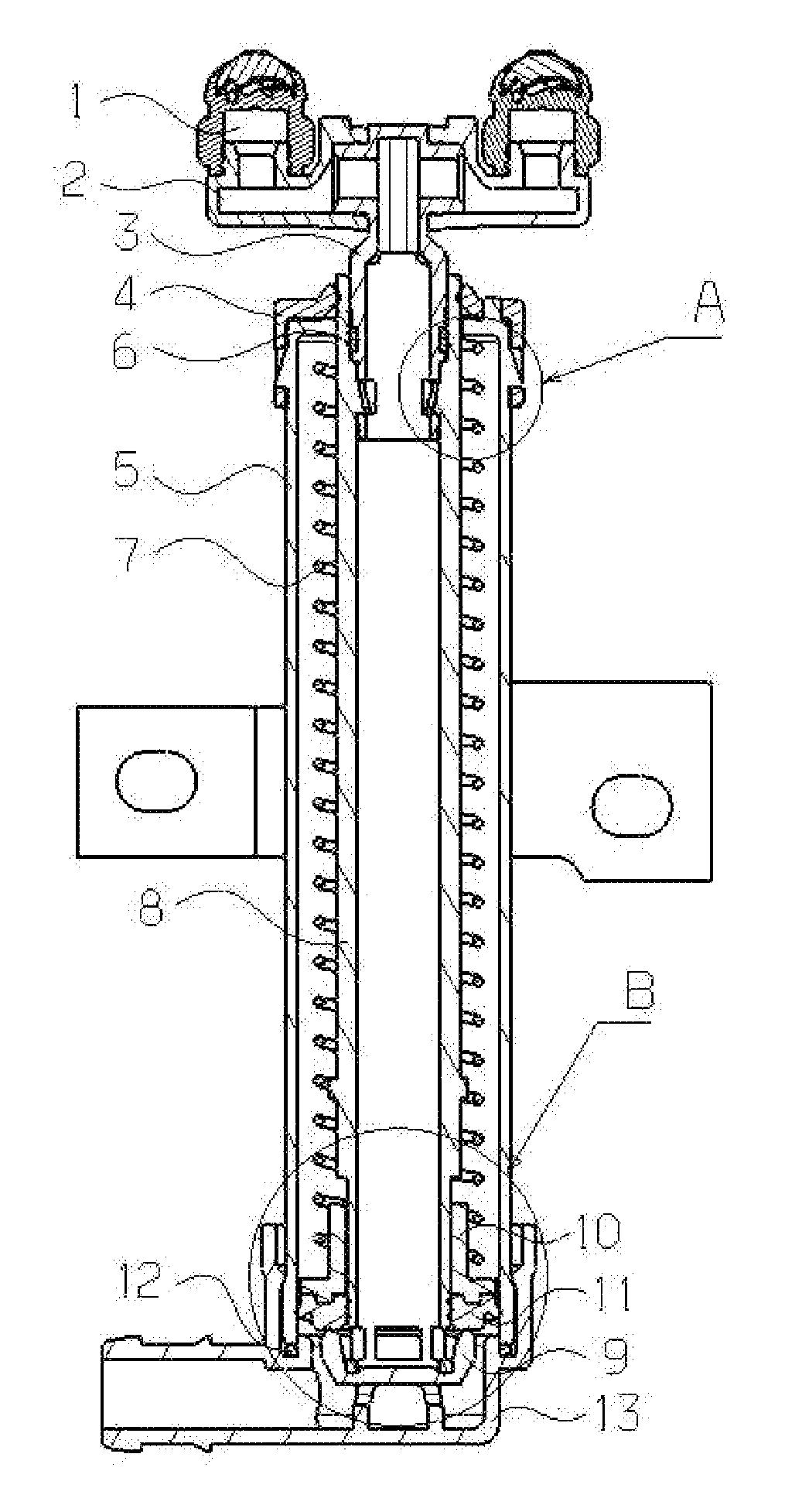
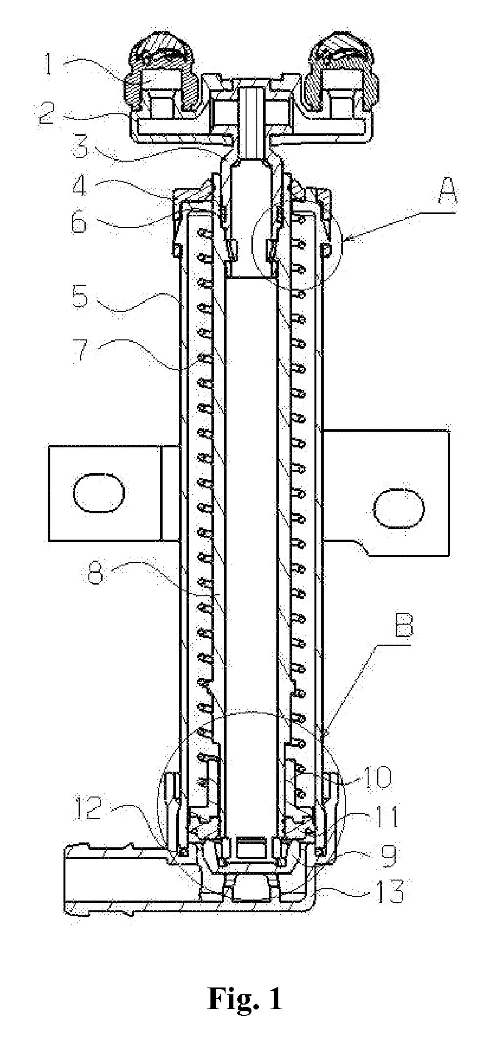
[0059]A vehicle headlight cleaning apparatus comprises: a casing which is consisted of a main cylindrical casing body 5 and a casing base 13 connected with the main cylindrical casing body, a seal component 12 is arranged between the main cylindrical casing body 5 and the casing base 13, the base 13 is provided with a cleaning solution inlet 13-1 and steps for fixing a transmission guide rod base 9.

[0060]A transmission guide rod 8 is of a cylinder structure and provided with openings on the front and the rear sides; the front opening is in a shape of a regular hexagon, which has the function of guiding and is matched with a nozzle holder 3; the rear opening allows the entry of cleaning solution while a movable seal valve is opened and is fixedly connected with the transmission guide rod base. The rear end of the transmission guide rod 8 is provided with a lug boss 8-1 which has position limiting effect.

[0061]The lower end of the transmission guide rod 8 is equipped with the movable ...

embodiment 2

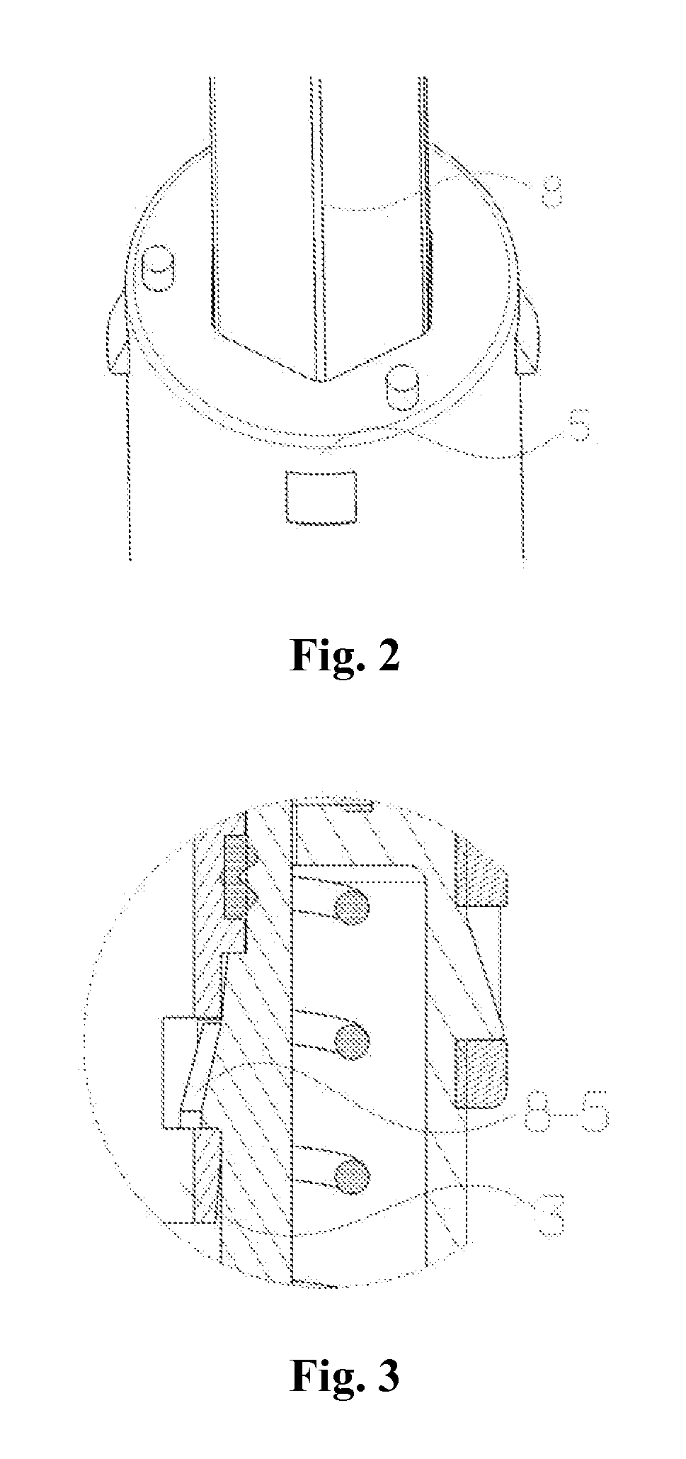
[0076]As shown in FIG. 3, a vehicle headlight cleaning apparatus of the invention is manufactured in the same processes of embodiment 1 except that the reverse-buckle 8-5 of the transmission guide rod is provided with a hook and a nozzle seal ring 6 to guarantee that the nozzle holder is reliably fixed in the transmission guide rod 5.

embodiment 3

[0077]The vehicle headlight cleaning apparatuses as embodiment 1 and embodiment 2 of the invention are installed at the bottom side of a passenger car headlight to make the cleaning nozzle face the signal face of the headlight and then carry out cleaning of the signal face. This is a convenient cleaning method with great cleaning effect.


PUM


Abstract

The invention relates to a vehicle headlight cleaning apparatus. A main body of the cleaning apparatus is of a cylindrical structure and internally provided with a compression spring and a movable seal valve which is matched with the inner wall of a casing of the cleaning apparatus. Both ends of the spring are respectively fixed on the end part of the cleaning apparatus and a spring fixing seat of the movable seal valve. When cleaning solution flows in the cleaning apparatus through a cleaning solution inlet on a base, the pressure of the cleaning solution overcomes the spring force of the compression spring and drives a transmission guide rod, the movable seal valve and a nozzle to move together, and the transmission guide rod stops when moving to a limit position. The pressure of the cleaning solution increases continuously, then the movable seal valve is opened under the pressure of the cleaning solution, the cleaning solution sprays out through the transmission guide rod and the nozzle, and a complete cleaning circuit is formed. When cleaning is finished, the pressure of the cleaning solution disappears, the movable seal valve is closed under the function of the compression spring, the transmission guide rod retracts into the casing till to an initial position, and the whole cleaning is finished. The invention has small and exquisite appearance, light weight, reliable work and high cleaning efficient.

Description

FIELD OF THE INVENTION[0001]The invention relates to a vehicle headlight auxiliary apparatus, in particular to a vehicle headlight cleaning apparatus. The cleaning apparatus of the invention is especially suitable for cleaning gas discharge lamps.BACKGROUND OF THE INVENTION[0002]With a large number of gas discharge lamps applied in medium-and-high grade car market in China, the requirements on headlight safety is more and more strict standard. Therefore, most of Chinese medium-and-high grade cars are equipped with headlight cleaning apparatus. Especially, a headlight such as a gas discharge lamp is easy to be contaminated during running process and causes glare for a driver counterpart, and further might causes accident. Therefore, to equip a cleaning apparatus on a headlight of a gas discharge lamp is necessary; meanwhile, China has already compulsorily executed provision that a high-brightness light source must be equipped with a headlight cleaning apparatus.[0003]So far, lots of ...

Claims


Application Information

Patent Timeline
IPC IPC(8): B60S1/56
CPCB05B1/20B05B1/3006B60S1/528B05B1/3436B05B1/304
Inventor GUO, TIANZHONGWANG, CHAOZHU, MINGHAU
Owner HASCO VISION TECHNOLOGY CO LTD
Why Eureka
Try Eureka