Molding system, method and articles formed thereby

a molding system and molding material technology, applied in the field of molding materials and articles formed thereby, can solve the problems of difficulty in adjusting the shape of the cushioning material to the shape of the obj

Inactive Publication Date: 2011-11-17
POLYWORKS
View PDF8 Cites 19 Cited by
  • Summary
  • Abstract
  • Description
  • Claims
  • Application Information

AI Technical Summary

Benefits of technology

[0005]A need exists in the art for improved methods of making polymeric articles.

Problems solved by technology

For objects with non-planar and / or complex shapes, it can be difficult to tailor the shape of the cushioning material to conform to the shape of the object.
In addition, many frequently used objects comprise materials that are hard to the human touch and / or result in friction when disposed against a human body, especially in repetitive motions.
For example, many frequently used objects comprise materials that are hard to the human touch and / or result in friction when disposed against a human body, especially in repetitive motions.

Method used


Image

  • Molding system, method and articles formed thereby
  • Molding system, method and articles formed thereby
  • Molding system, method and articles formed thereby

Examples


working examples

Example 1

[0079]Formation of an innersole. A metal mold defining thirty six (36) heel liners was selected for use in the Desma machine. The mold comprised a recessed region of about 0.020″, and a gasket spaced apart both from the perimeter of the mold edge and from the recessed region. The dimensions of each of the 36 mold units were about 4 inches by about ½ inch, and the depth of the mold units was uniform. A TPU sheet having a thickness of 0.004″ (Deerfield Urethane PS3110) was installed on a press, and stretched across the top of the mold. The TPU sheet was heated under a heater at 430° F. for 14 seconds, and then a gel precursor was dispensed onto the TPU sheet. A barrier layer was then placed over the top of the gel precursor.

[0080]The mold cover closing cycle was initiated, which applied pressure to the gel precursor, so that it began to spread laterally in the mold. When the gel precursor reached the edge of the mold, a vacuum was applied to the underside of the TPU sheet, to...

example 2

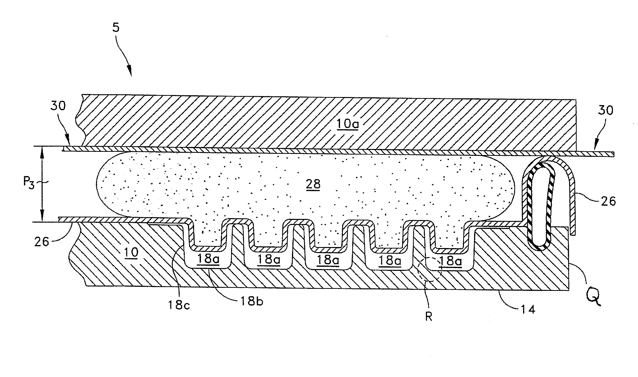
[0082]Formation of a gel seat pad. A metal mold defining a single seat pad was selected for use in the Desma machine. The seat pad was 16″ long, 13″ wide by ¼″ thick, and comprising about 190 pods. After installation on a press a sheet of 0.004″ thick TPU, such as Deerfield Urethane PS3110, the TPU film was stretched across the top of the mold, and heated under a heater at 430° F. for 14 seconds. A gel precursor was then dispensed onto the TPU sheet. A stabilization layer was then placed over the top of the gel precursor.

[0083]The mold cover closing cycle was initiated, which applied pressure to the gel precursor, so that it began to spread laterally in the mold. When the gel precursor reached the edge of the mold, a vacuum was applied to the underside of the TPU sheet, to draw it into the mold cavities, which was initiated about six (6) second after the mold closing cycle was initiated. The complete mold cover closing cycle was about ten (10) seconds. Thereafter, the part was allow...

example 3

[0084]Formation of a Frothed Foam Elbow Pads. A metal mold defining a 4 elbow pads was selected for use in a Desma rotary molding machine, and bolted to the support plates at each molding station. Each elbow pad was 8.5″ long, 6″ wide by 0.25″ thick, and comprising about 11 pods. After the mold bases were installed, a sheet of 0.004″ thick TPU, such as Deerfield Urethane PS3110, was stretched across the top of the mold base at the first station, and heated to about 205° F.

[0085]In the material mixing and dispensing system, the components of a polyurethane foam (Poron XRD, available from Rogers Corporation) were circulated in subsystems A and B, and thereafter, valves M and N were opened, allowing the polyol and isocyanate to flow into mixing chamber 730, along with compressed nitrogen from the source of compressed gas. The material components were mechanically mixed together and with the compressed nitrogen to form cellular, frothed foam material formulation with a density in the ra...


PUM

PropertyMeasurementUnit
thicknessesaaaaaaaaaa
pressureaaaaaaaaaa
elongationaaaaaaaaaa

Abstract

Disclosed herein is a molding system that facilitates the molding of very thick products from materials such as gel and/or mechanically frothed foam, substantially free of visual defects, such as air bubbles, by controlling the rate of mold closure and/or interrupting the mold closure.

Description

RELATED CASES[0001]The present application is a continuation-in-part of U.S. patent application Ser. No. 11,644,266, which was filed on Dec. 23, 2006, and of U.S. patent application Ser. No. 12,423,174, which was filed on Apr. 14, 2009, both of which are incorporated herein by reference in their entirety; and priority is claimed herein to U.S. Provisional Patent Application No. 61 / 294,716, which was filed on Jan. 18, 2010, which is incorporated herein by reference in its entirety.TECHNICAL FIELD[0002]The present disclosure relates to systems and methods of molding materials and articles formed thereby.RELATED ART[0003]Many different types of products benefit from the inclusion of a material that provides cushioning for, among other things, impact and vibration dampening, resistance to compression, deflection, friction reduction, and the like. For objects with non-planar and / or complex shapes, it can be difficult to tailor the shape of the cushioning material to conform to the shape ...

Claims


Application Information

Patent Timeline
Patent Type & Authority Applications(United States)
IPC IPC(8): B29C43/18B29C43/56B32B3/10B28B3/02
CPCB29D35/148A43B13/187Y10T428/24612B29C43/18B29D35/142A43B13/189B29C2043/5833B29B7/7404B29B7/7433A41D13/08A43B17/003A47C7/02B29B7/002B29B13/02B29C43/184B29C43/56B29C65/48B29C2043/563B29D35/14B29K2075/00B29K2105/04B29K2105/20B29K2701/12B29K2995/0089B29K2995/0091B29L2031/50
Inventor FOX, RICHARD B.GAUDET, JAMES E.
Owner POLYWORKS
Why Eureka
Try Eureka