Imprint apparatus and method of manufacturing article

a technology of printing apparatus and manufacturing method, which is applied in the direction of photomechanical apparatus, manufacturing tools, instruments, etc., can solve the problem that the detection light for detecting the position of the mark is often weak

Inactive Publication Date: 2011-11-17
CANON KK
View PDF2 Cites 29 Cited by
  • Summary
  • Abstract
  • Description
  • Claims
  • Application Information

AI Technical Summary

Problems solved by technology

When the mark has a layered structure formed on it, detection light for detecting the position of the mark often weakens be

Method used


Image

  • Imprint apparatus and method of manufacturing article
  • Imprint apparatus and method of manufacturing article
  • Imprint apparatus and method of manufacturing article

Examples


first embodiment

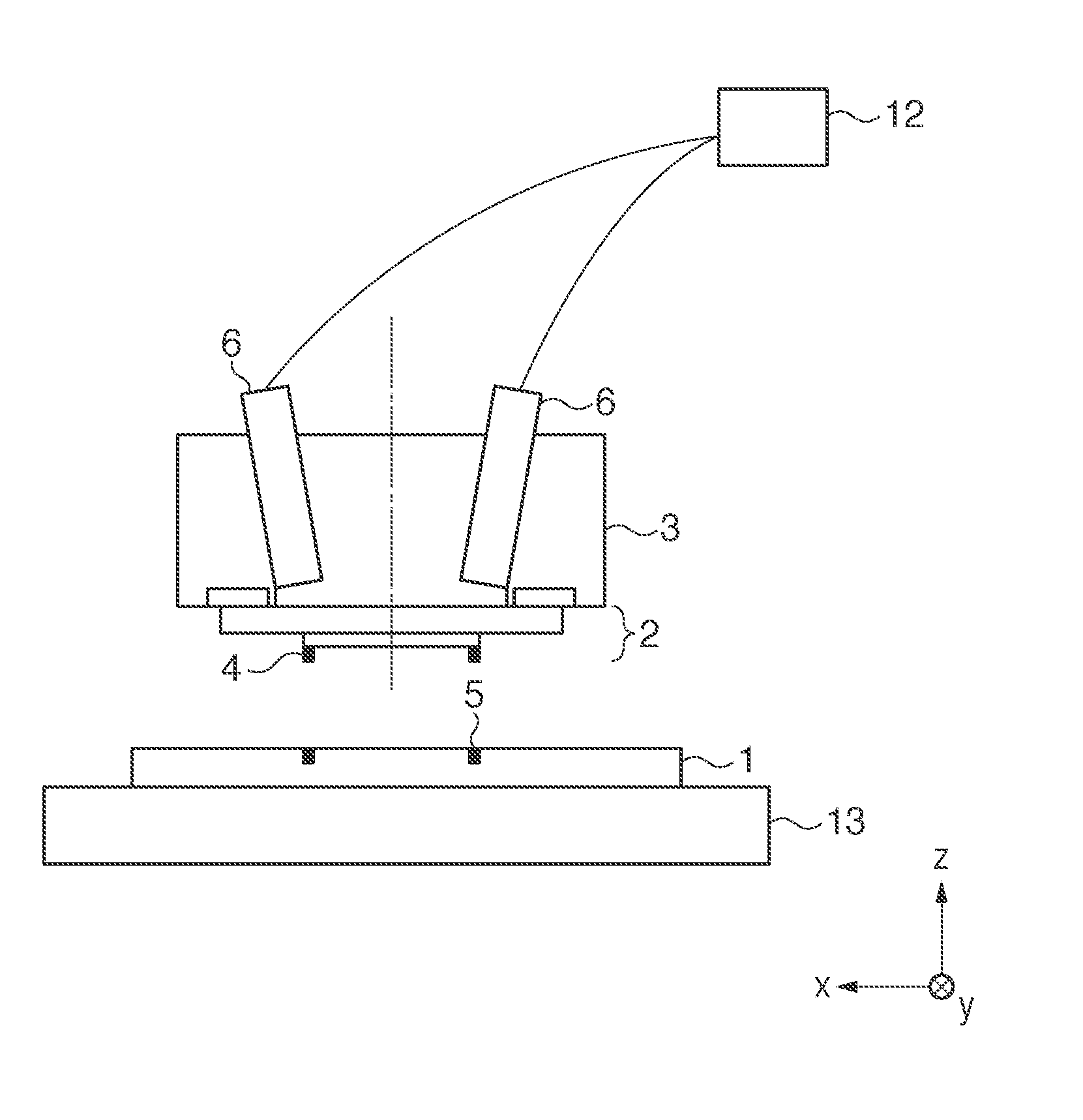
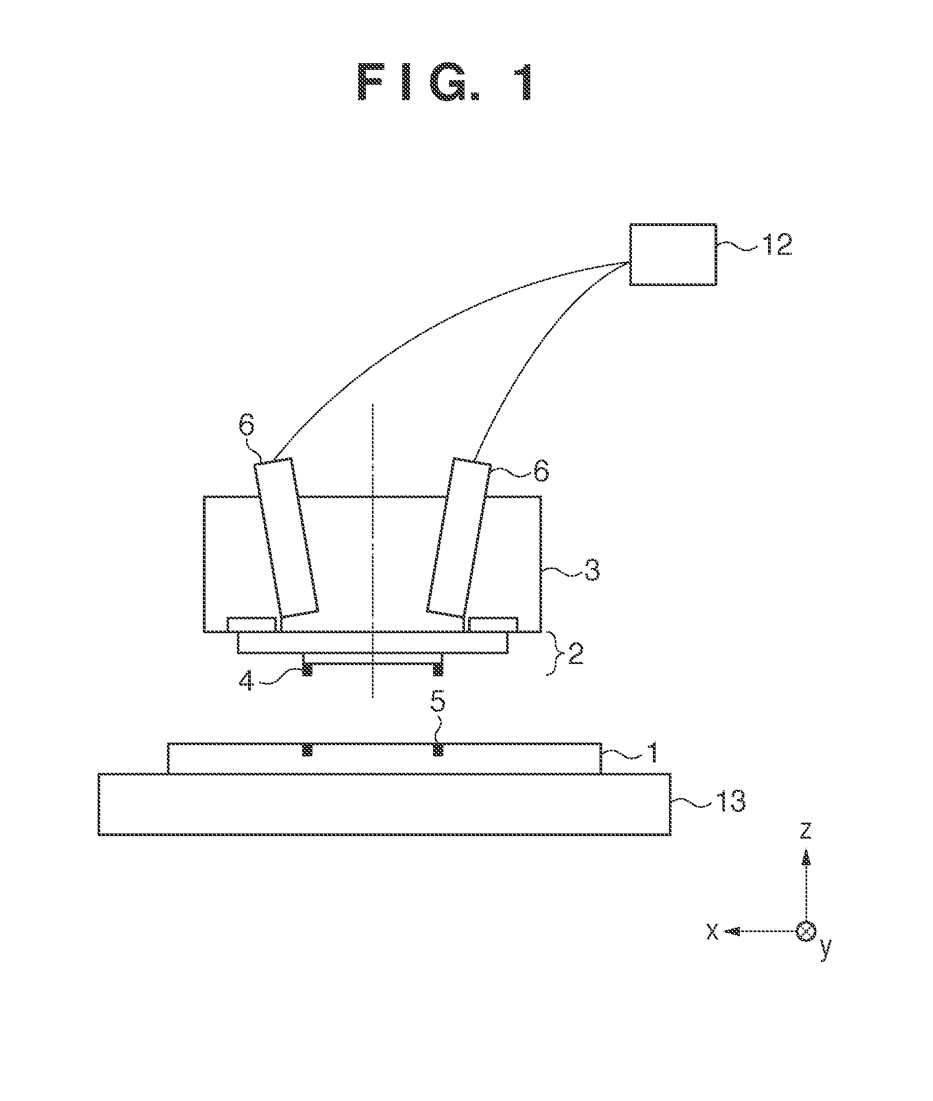
[0018]An imprint apparatus including a built-in detector according to the first embodiment will be described with reference to FIG. 1. The imprint apparatus performs an imprint process of dispensing an uncured resin onto a substrate 1 held by a substrate stage 13, pressing the pattern surface of a mold 2 against the resin, and curing the resin. The mold 2 is held by a holder (imprint head) 3. Detectors (scopes) 6 are placed in the holder 3. The scope 6 optically observes a mark (first mark) 4 formed on the mold 2 and a mark (second mark) 5 formed on the substrate 1, thereby detecting their relative positional relationship. The scope 6 is slightly tilted in order to ensure an optical path necessary to illuminate the resin from above with light for curing the resin in an imprint process. An adjusting device 12 including a driving mechanism and its controller can adjust the angle of the optical axis of the scope 6. The scope 6 uses, for example, a half prism 7 to guide light emitted by...

second embodiment

[0032]A detector according to the second embodiment will be described with reference to FIG. 9. Upon irradiation with broadband light with intensities in a wide wavelength range, a mark 5 on a substrate exhibits the performance of a diffraction grating, so different wavelengths are diffracted by different angles. FIG. 9 shows this mechanism, in which the diffraction angle is based on equation (1), (2), or (4). The wavelength λ of diffracted light is λ14 and the mark 5, thereby searching for a wavelength and a tilt angle which are optimum for measurement. Examples of indices of the optimum tilt angle are the intensity and contrast of the moire signal. A measurement method in this embodiment is the same as in the first embodiment.

third embodiment

[0033]A detector according to the third embodiment will be described next with reference to FIG. 10. FIG. 10 shows a scope 6 for measuring only a mark 4 on a mold 2. As the scope 6, the same scope as in the first embodiment may be used or a dedicated scope may be separately provided. Because a force acts on the mold 2 upon pressing and releasing the mold 2 in an imprint process, the mold 2 may shift with respect to an imprint head 3. In this case, the position of the mold 2 must be measured in real time. The mark 4 used for alignment with a mark 5 on a substrate 1, and a mark 4′ used to measure the position of the mold 2 are formed on the mold 2 shown in FIG. 10. The marks 4 and 4′ are designed to have different optimum diffraction angles in measurement by changing the pitch.

[0034]As a measurement method, the mark 4′ may be directly measured in the form of an image or signal intensity. Also, a reference mark 10 shown in FIG. 10 may be placed at a position optically conjugate to the ...


PUM

PropertyMeasurementUnit
Angleaaaaaaaaaa

Abstract

An imprint apparatus includes a detector and an adjusting device. A second mark formed on a substrate includes a grating pattern having grating pitches in first and second directions which are respectively parallel to first and second axes which are parallel to a pattern surface of a mold and orthogonal to each other. A first mark formed on the mold includes a grating pattern having a grating pitch in the first direction. The first and second marks have different grating pitches in the first direction. The detector includes an image sensor, and an optical system which forms a moire fringe on an image sensing surface of the image sensor. The adjusting device adjusts, in a plane including the second axis and a third axis that is perpendicular to the first and second axes, an angle between the optical axis of the detector and the third axis.

Description

BACKGROUND OF THE INVENTION[0001]1. Field of the Invention[0002]The present invention relates to an imprint apparatus and a method of manufacturing an article.[0003]2. Description of the Related Art[0004]Imprint techniques are coming into practical use as one of the nanolithographic techniques intended for mass production of magnetic storage media and semiconductor devices. An imprint apparatus uses a mold on which a fine pattern is formed as an original, and presses the mold against a resin (imprint material) dispensed on a substrate such as a silicon wafer or a glass plate to transfer the pattern of the mold onto the substrate, thereby forming a fine pattern on the substrate. At this time, a detector which measures the relative position between a mark formed on the mold and that formed on the substrate is used to align the mold and the substrate. Especially a measurement device which uses moire fringes (moire signal) generated by these two marks is useful because it can achieve hi...

Claims


Application Information

Patent Timeline
IPC IPC(8): G01B15/00B29B15/00
CPCB82Y10/00B82Y40/00G03F9/7076G03F9/7042G03F9/7049G03F7/0002B29C33/38B29C33/42
Inventor SATO, HIROSHI
Owner CANON KK
Why Eureka
Try Eureka