Motor driving circuit

Active Publication Date: 2011-11-17
ROHM CO LTD
View PDF4 Cites 29 Cited by
  • Summary
  • Abstract
  • Description
  • Claims
  • Application Information

AI Technical Summary

Benefits of technology

[0014]With such an embodiment, by adjusting the bias signal to be applied to the Hall sensor, such an arrangement is capable of stabiliz

Problems solved by technology

The aforementioned components are monolithically integrated on a single semiconductor substrate.

Method used


Image

  • Motor driving circuit
  • Motor driving circuit
  • Motor driving circuit

Examples


first embodiment

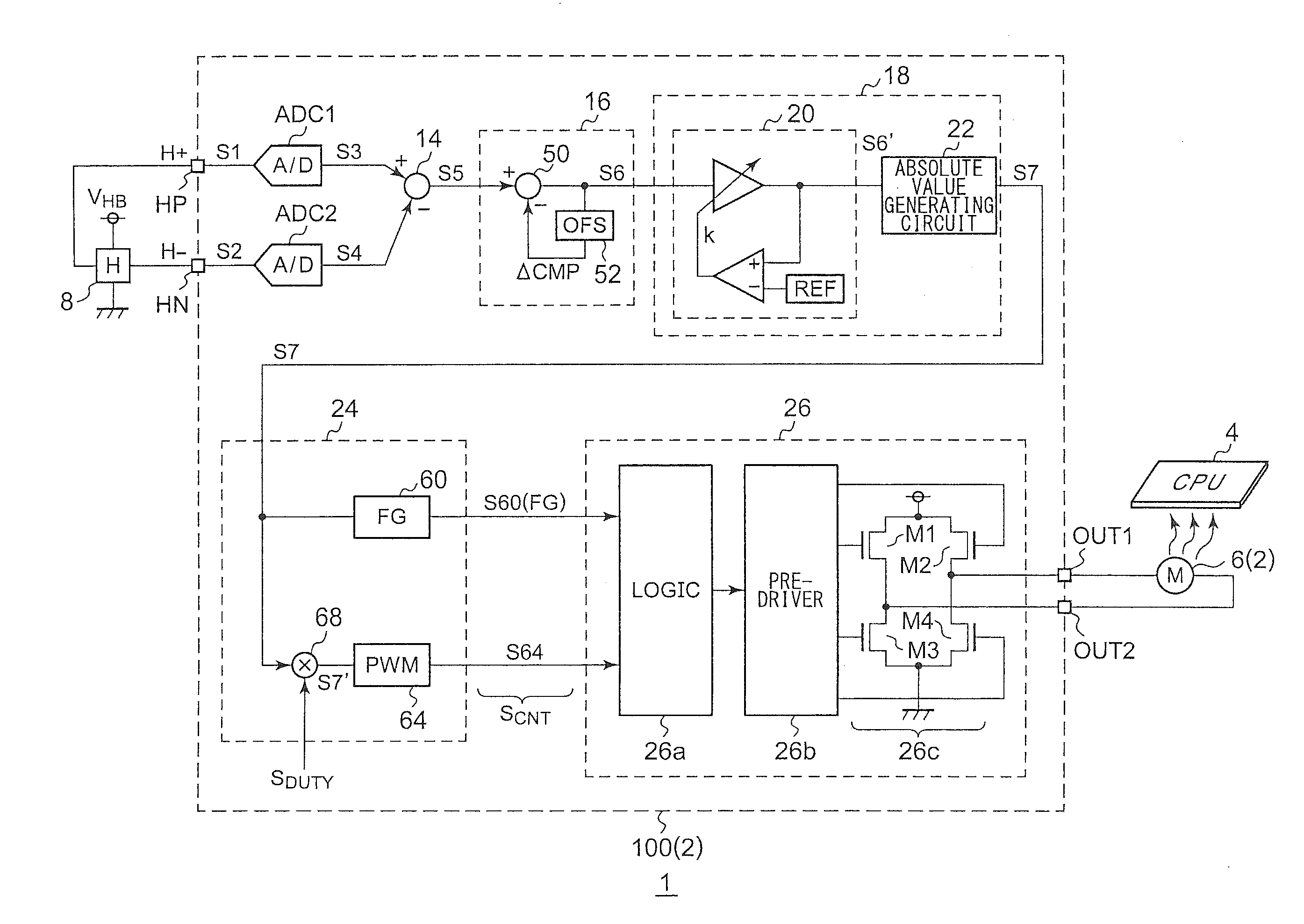
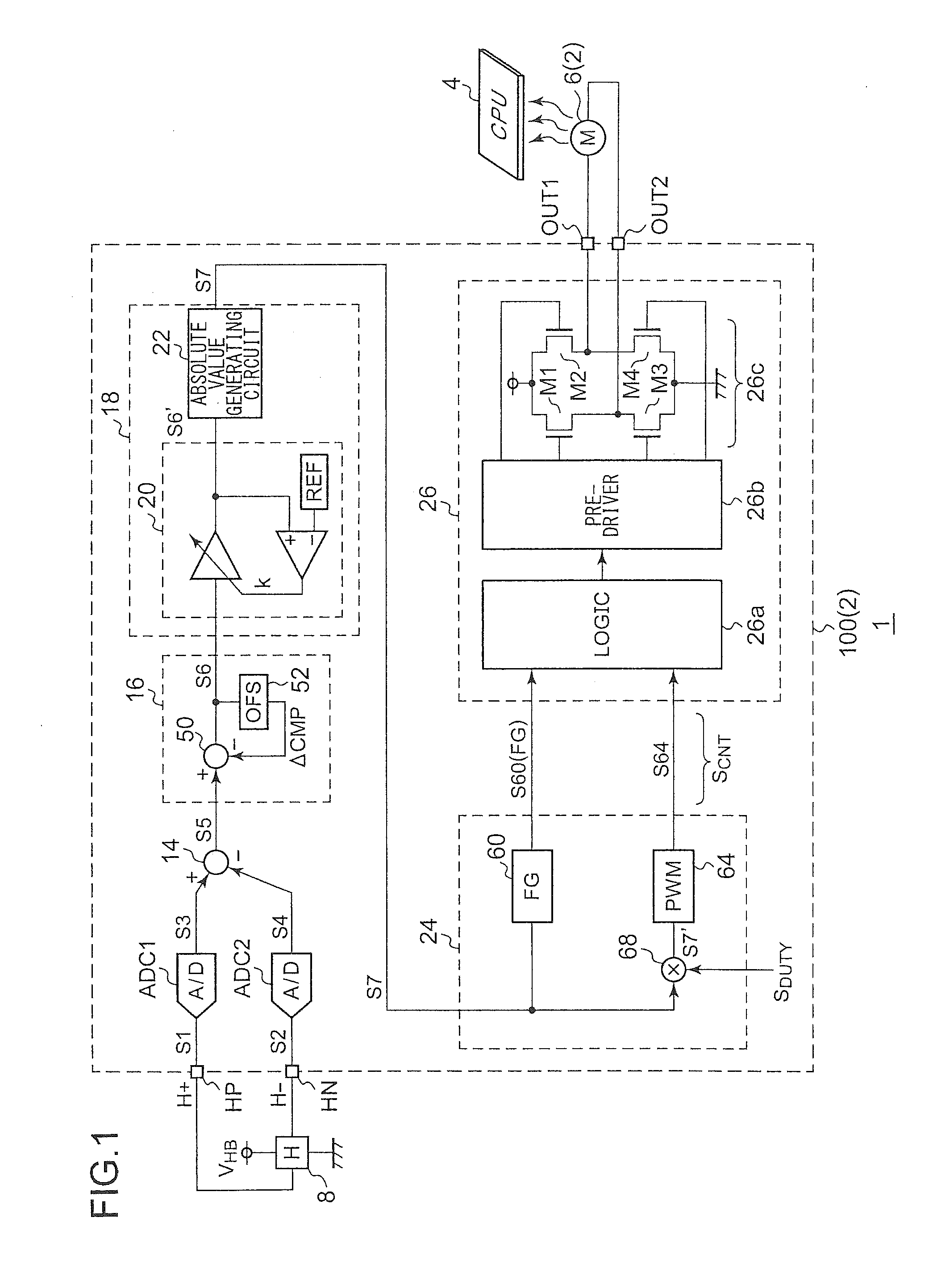
[0036]FIG. 1 is a circuit diagram which shows a configuration of an electronic device 1 including a driving IC 100 according to a first embodiment. The electronic device 1 is configured as a desktop computer, a laptop computer, a workstation, a game device, an audio device, a video device, or the like, for example, and includes a cooling apparatus 2 and a CPU (Central Processing Unit) 4. The cooling apparatus 2 includes a fan motor 6 arranged such that it faces the CPU 4, and a driving IC 100 configured to drive the fan motor 6.

[0037]The driving IC 100 is configured as a function IC integrated on a single semiconductor chip. The driving IC 100 is connected to a Hall sensor 8 arranged at a position at which it receives the magnetic field from the rotor of the fan motor 6, in addition to being connected to the fan motor 6 to be driven. A Hall bias voltage VHB is applied to the Hall sensor 8. The Hall sensor 8 generates a Hall signal comprising a complimentary first signal S1 (H+) and ...

second embodiment

[0081]Description will be made in the second embodiment regarding a rotational driving control operation for the fan motor 6 according to the temperature or an external control signal. FIGS. 6A through 6C are circuit diagrams each showing a configuration of a driving IC 100 according to the second embodiment.

[0082]In FIG. 6A through 6C, the same circuit blocks as those shown in FIG. 1 are not shown as appropriate. FIG. 6A is a circuit diagram which shows a configuration of a driving IC 100a configured to perform a rotational driving control operation according to the temperature.

[0083]The driving IC 100a includes a thermistor terminal TH, a third A / D converter ADC3, and a control instruction circuit 72.

[0084]The thermistor terminal TH is connected to a thermistor RTH biased by a reference voltage VREF. The thermistor terminal TH receives, as an input signal, an analog temperature detection voltage VTH that corresponds to the temperature. The third A / D converter ADC3 performs analog / ...

third embodiment

[0091]In some cases, heat generation of a CPU to be cooled, the temperature thereof, the thermal runaway threshold voltage thereof, and so on, differ for each CPU. Accordingly, the rotational speed of the cooling fan is preferably set in a flexible manner according to the target to be cooled. Description will be made in the third embodiment regarding a technique for providing a flexible rotational speed control operation.

[0092]FIG. 7 is a circuit diagram which shows a part of a configuration of a driving IC 100d according to a third embodiment

[0093]The driving IC 100d shown in FIG. 7 includes a PWM pulse signal input terminal PWM instead of the duty ratio control terminal DUTY shown in FIGS. 6B and 6C. An external PWM signal PWM subjected to pulse width modulation is input to the PWM pulse signal input terminal PWM. The driving IC 100 performs PWM driving of the fan motor 6 according to the duty ratio of the external PWM signal. The duty ratio of the external PWM signal PWM is set i...


PUM


Abstract

First and second A/D converters perform analog/digital conversion of first and second signals of a Hall signal so as to generate third and fourth signals as digital signals. A differential conversion circuit generates a fifth signal as a single-ended signal that corresponds to the difference between the third and fourth signals. An offset correction circuit corrects offset of the fifth signal so as to generate a sixth signal. An amplitude control circuit stabilizes the amplitude of the sixth signal to a predetermined target value, and generates its absolute value, thus generating a seventh signal. A control signal generating unit generates a control signal upon the seventh signal. A driver circuit drives a motor according to the control signal.

Description

BACKGROUND OF THE INVENTION[0001]1. Field of the Invention[0002]The present invention relates to a motor driving apparatus.[0003]2. Description of the Related Art[0004]As a cooling fan motor, a spindle motor configured to rotationally drive an optical or a magnetic disk, or a capstan motor employed in a tape recording apparatus, a DC motor is employed. Typical DC motors each include a rotor having a permanent magnet and a stator having a coil. By controlling electric current to be supplied to the coil, such a DC motor is rotationally driven.[0005]In order to detect the rotational position of the rotor of the DC motor, a Hall sensor (Hall element) is employed. Such a Hall sensor generates a pair of Hall signals that change in a complementary manner according to the position of the rotor of the motor (which will be collectively referred to simply as a “Hall signal”). Hall sensor mounting motors are known including a Hall sensor mounted on a stator.[0006]A motor driving circuit switche...

Claims


Application Information

Patent Timeline
IPC IPC(8): H02P6/16H02P6/06H02P6/08H02P6/12H02P6/26
CPCH02P6/16H02P6/085
Inventor SHIMIZU, TATSUROISHII, HIROYUKIKOMURA, NOBUOSUZUKI, TOSHIYA
Owner ROHM CO LTD
Why Eureka
Try Eureka