
Apparatus for holding digital dental x-ray sensor and method of making same

a technology for dental x-ray sensors and accessories, applied in the field of accessories for holding dental x-ray sensors and a method of making same, can solve the problems of styrofoam pieces or stabe® typically being much larger than that used for traditional films, affecting the quality of dental x-rays, and affecting the patient's oral health, so as to prevent lateral force

Inactive Publication Date: 2011-11-17
INNOVATION 101
View PDF2 Cites 14 Cited by
  • Summary
  • Abstract
  • Description
  • Claims
  • Application Information

AI Technical Summary

Benefits of technology

[0009]The need exists, therefore, for a means to prevent the lateral force that often causes unintended bite-piece movement.

Problems solved by technology

For instance, film processing takes valuable time and includes the use of chemicals that must be purchased and then later disposed of The film itself is only used once and then stored in the patient's file, adding the cost of purchase and storage.
In order to obtain imaging data from the sensor, the sensor often includes a data cable that extends therefrom (some wireless devices are known but tend to not be used in the industry because of transmission issues, cost and risk of being inadvertently disposed of, and because of possible theft by patients, to name a few examples).
Because the sensor is used numerous times in an imaging session, a styrofoam piece or Stabe® is typically not useable as a bite-block because styrofoam irreversibly distorts after each mandibular force sufficient to stabilize the sensor is applied.
Also, in order to accommodate the digital sensor, a styrofoam piece or Stabe® typically is much larger than that used for traditional film and may not fit comfortably into the mouth of a patient.
However, the data cable for digital radiography can cause interference in the oral cavity and upon application of the mandibular force the digital sensor may be caused to move out of its desired position.
That is, as a patient applies a lateral or biting force to the bite-block, the cable extending from the sensor may interfere with a patient's lips or teeth, as examples, causing motion of the sensor.
Because the bite-block is typically fabricated from a hard plastic, and because of the cable interference, motion of the sensor may occur while imaging data is obtained, causing blurring in the image.
As a result, the image needs to be retaken, adding cost and time to the process, and adding radiation exposure to the patient.

Method used


Image

  • Apparatus for holding digital dental x-ray sensor and method of making same
  • Apparatus for holding digital dental x-ray sensor and method of making same
  • Apparatus for holding digital dental x-ray sensor and method of making same

Examples


Embodiment Construction

[0020]Forms of the bite-piece are shown by the figures as described with respect to a digital dental x-ray sensor assembly. However, it is to be understood that the invention is not to be so limited, and that the invention is applicable to any device where a mandibular vertical force may be applied that causes an x-ray sensitive device to move after that device has been aligned with an x-ray source.

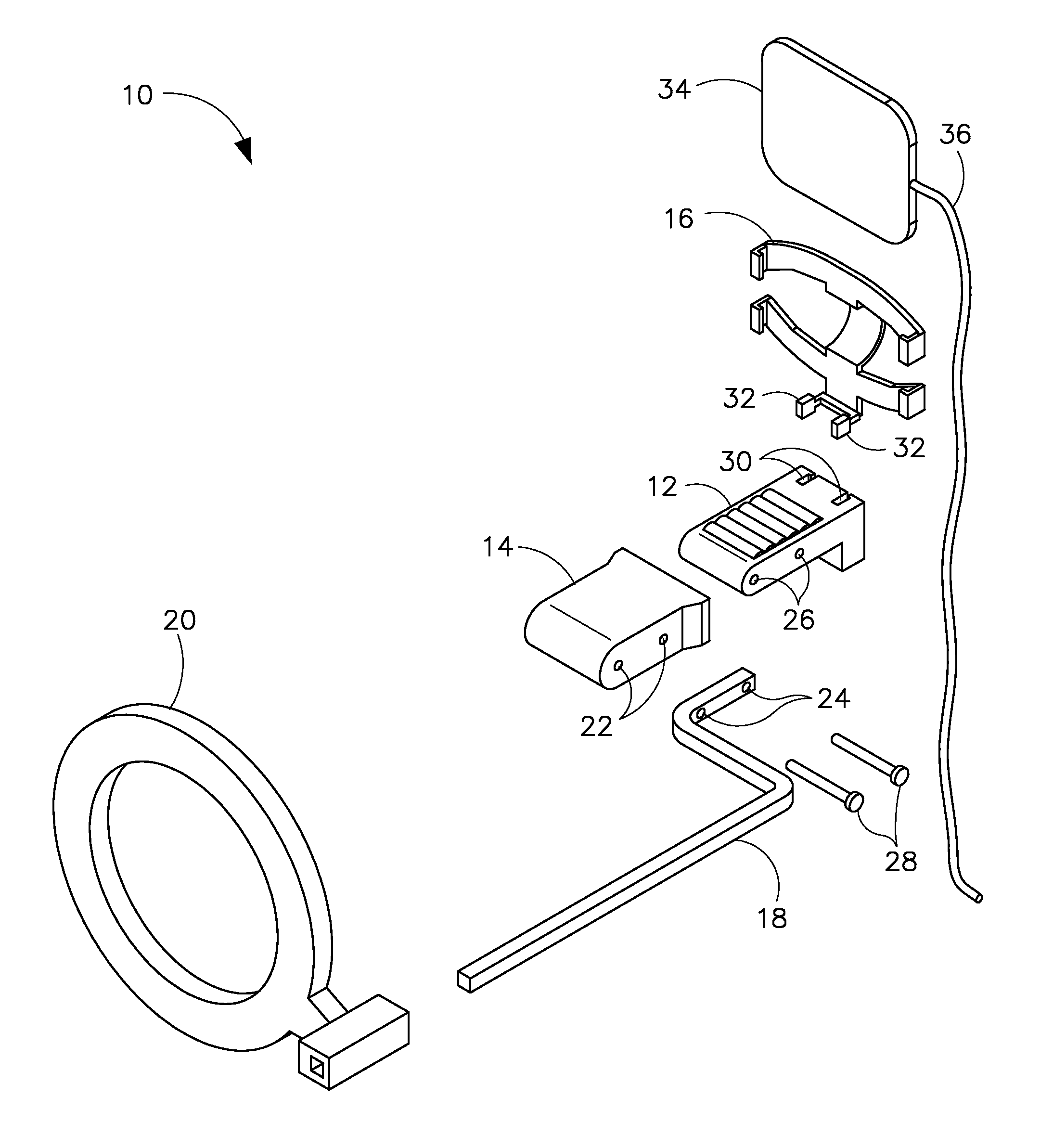
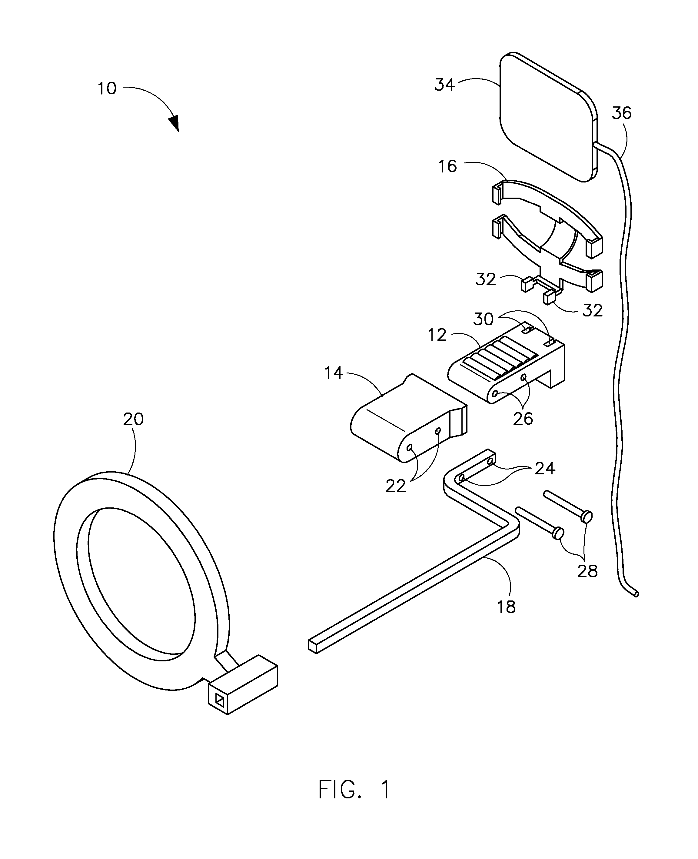
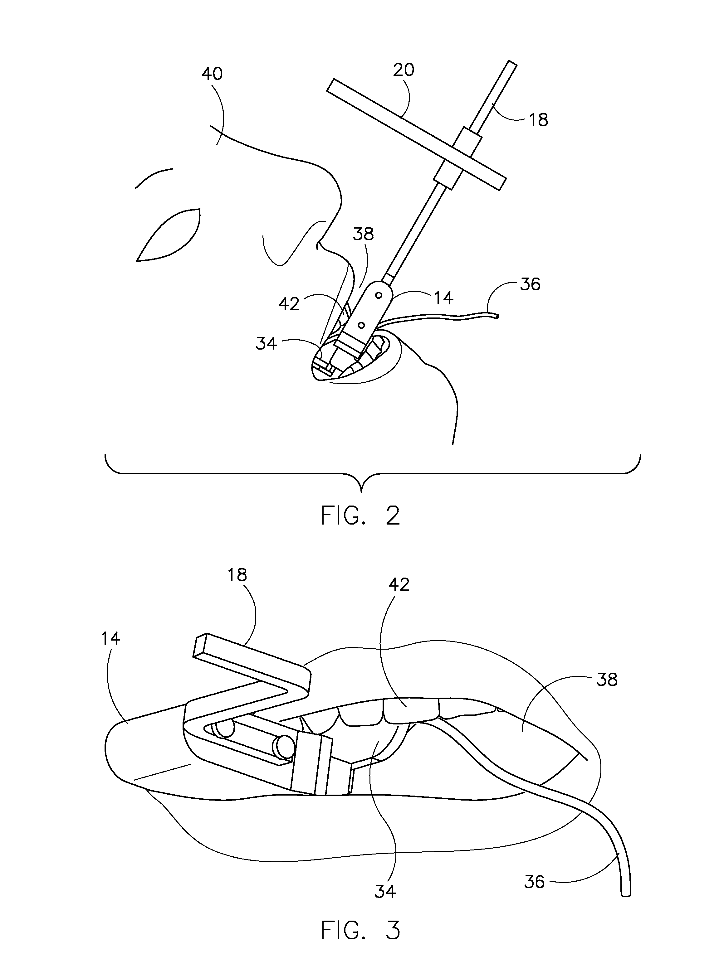
[0021]FIG. 1 is an illustration of a dental x-ray sensor assembly according to an embodiment of the invention. FIG. 1 illustrates an assembly 10 that includes a bite-piece or bite-block 12, a boot or bite-block cover 14, a sensor holder 16, and a support structure 18 coupled to an aiming ring 20. Bite-block 12 is fabricated from a hard, non-deformable plastic such as polycarbonate having a hardness of, for instance, 117 Rockwell R. However, bite-block 12 is not so limited and may be any material having sufficient structural integrity and hardness to support bite-block cover 14, such as a ...


PUM

PropertyMeasurementUnit
friction coefficientaaaaaaaaaa
biting forceaaaaaaaaaa
hardnessaaaaaaaaaa

Abstract

A dental x-ray sensor assembly includes a bite block used for digital imaging, wherein a surface of the bite block includes a deformable material that readily returns to an undeformed position after a biting force is removed therefrom.

Description

CROSS-REFERENCE TO RELATED APPLICATION[0001]The present application is a non-provisional of, and claims priority to, U.S. Provisional Application 61 / 333,375 filed May 11, 2010, the disclosure of which is incorporated herein.BACKGROUND[0002]Embodiments of the invention relate generally to dental x-ray sensor assembly, and more specifically to an apparatus for holding a dental x-ray sensor and a method of making same.[0003]Traditionally, dental radiographs are made using an x-ray sensor that includes a film that is positioned within a patient's oral cavity and aligned to take an x-ray image of certain teeth using a film holder. The film is positioned such that x-rays directed toward the film first pass through the teeth and impinge upon the film. An image generated therefrom is based on an amount of x-ray attenuation that occurs, which depends on varying anatomical densities through which the x-rays pass.[0004]In order to properly position and align the sensor with respect to the targ...

Claims


Application Information

Patent Timeline
Patent Type & Authority Applications(United States)
IPC IPC(8): A61B6/14B23P11/00
CPCA61B6/145Y10T29/49826A61B6/4435A61B6/512
Inventor FELTZ, KENT A.MATTSON, JEFFREY J.
Owner INNOVATION 101
Learn More