Electric power steering device

a technology of electric power steering and peripheral faces, which is applied in the direction of gearing details, rigid support of the bearing unit, transportation and packaging, etc., can solve the problems of presenting discomfort, unpleasant sensations, etc., and achieve the reduction or elimination of vibrations and abnormal noise, the effect of reducing or preventing stick slippag

Inactive Publication Date: 2011-11-24
NSK LTD
View PDF15 Cites 10 Cited by
  • Summary
  • Abstract
  • Description
  • Claims
  • Application Information

AI Technical Summary

Benefits of technology

[0028]According to the electric power steering device of the present invention, which is configured as described above, the occurrence of stick slip between the outer peripheral face of the rotation shaft and the inner peripheral face of the inner ring of the rolling bearings can be reduced or prevented.
[0029]That is to say, in the present invention, a lubricant, an elastic material, or the like, is interposed between the inner peripheral face of the inner rings of the rolling bearings and the outer peripheral face of the rotation shaft, and the friction coefficient between these peripheral faces is changed. Consequently, even if this rotation shaft becomes likely to be displaced in the axial direction, as a result of these lubricants, elastic materials, or the like, the sliding or axial displacement between these peripheral faces can be made smooth, and the occurrence of stick slip can be reduced or prevented. As a result, a reduction or elimination of vibrations and abnormal noise such as “chattering” can be achieved, a smooth and comfortable steering sensation can be assured, and the situation where the driver is subjected to discomfort, unpleasant sensations, and the like, can be prevented.
[0030]In particular, there is a case which employs a configuration where, of the pair of rolling bearings that are provided on both axial direction sides of the worm wheel and which freely rotatably support the rotation shaft with respect to the housing, as the one rolling bearing present on the front end side of the rotation shaft sandwiching the worm wheel, a single row deep groove-type ball bearing is utilized instead of a four-point contact-type ball bearing, due to demands of cost reduction and torque reduction. Whereas, in regard to the other rolling bearing present on the rear end side of the rotation shaft, of the outer peripheral face of the rotation shaft, only one part of the front end side of the inner ring is externally fitted with respect to the large diameter portion adjacent to the front end side of the torque detecting concave and convex portions, and this is installed in a state with the fit between the inner peripheral face of the inner ring and the large diameter portion as a clearance fit. In this configuration, it becomes easier for stick slip to occur between the inner ring of the other rolling bearing and the large diameter portion, which is attributable to the rotation shaft becoming easily displaced at the time of usage, and the central axes of the inner ring of the other rolling bearing and the rotation shaft becoming easily tilted. As a result of the present invention, even in such a configuration, it is possible to reduce or prevent the occurrence of stick slip between the inner peripheral face of the inner ring of the other rolling bearing and the outer peripheral face of the rotation shaft.
[0031]Furthermore, in the present invention, by devising the face shape of the part of the outer peripheral face of the rotation shaft, where the lubricant is interposed between the rotation shaft and the inner peripheral face of the inner ring which constitutes the rolling bearing, the lubricant collects on this face. Therefore the lubricated state between these can be well maintained over a long period. As a result, the effect of reducing or preventing the occurrence of stick slip, which occurs between the outer peripheral face of the rotation shaft and the inner peripheral face of the inner ring, can be maintained over a long period.

Problems solved by technology

Moreover, accompanying such a stick slip between the peripheral faces, there is a possibility of vibrations and abnormal noise, such as “chattering”, to be generated, presenting discomfort, unpleasant sensations, or the like, to the driver.

Method used


Image

  • Electric power steering device
  • Electric power steering device
  • Electric power steering device

Examples


first embodiment

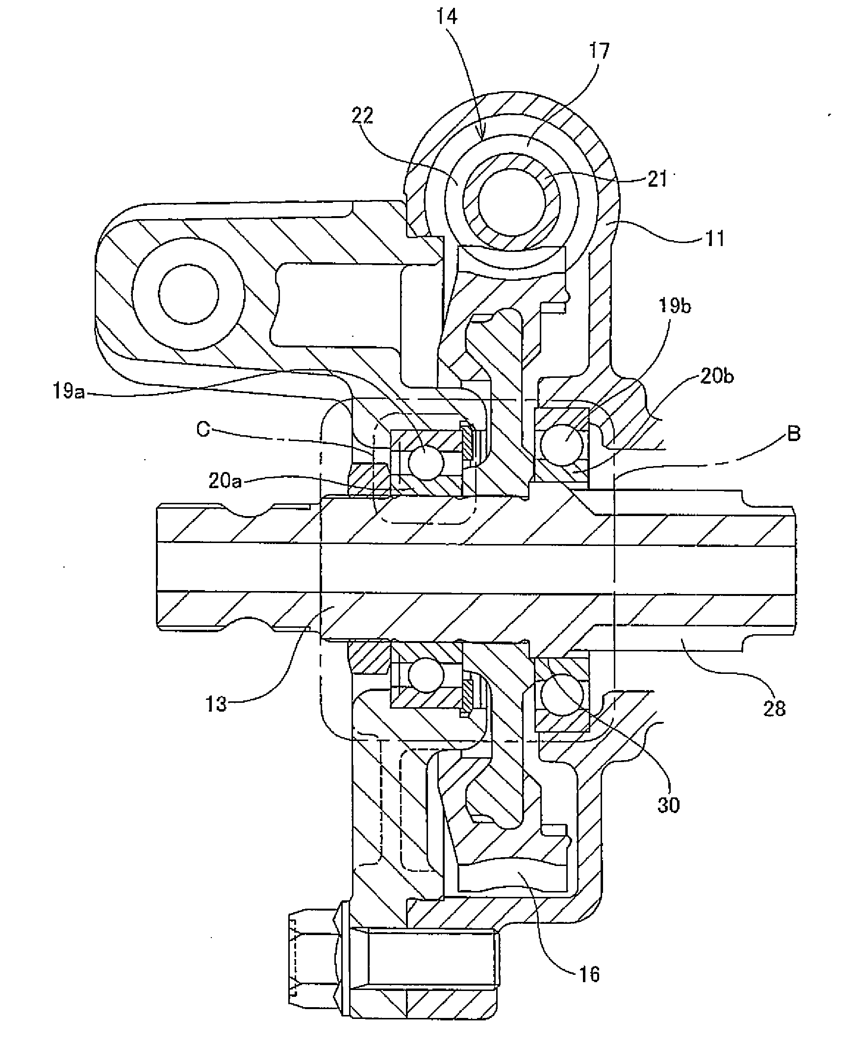
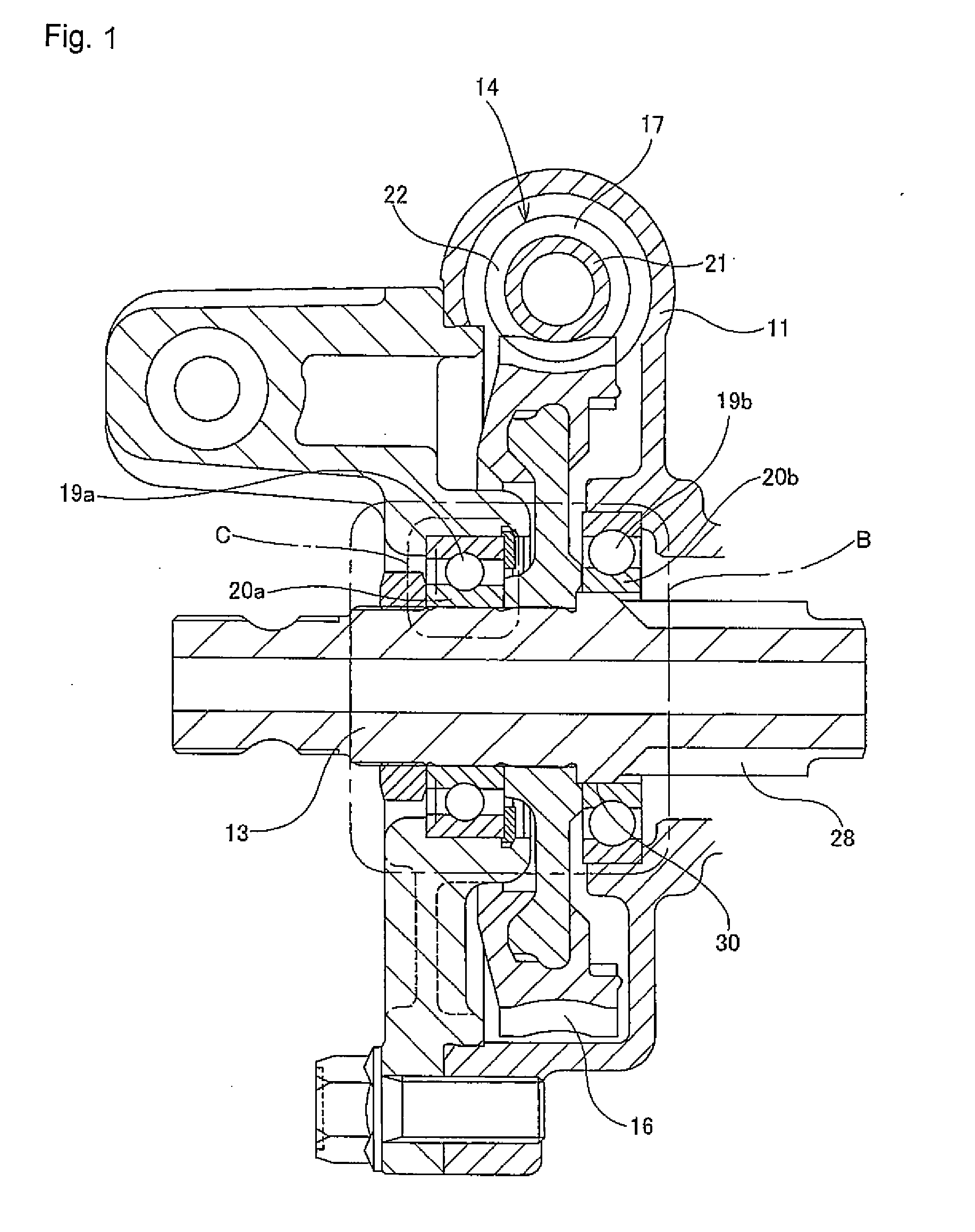
[0046]FIGS. 1 and 2 show a first embodiment of the present invention. The electric power steering device of the present example is characterized by a configuration for making stick slip more difficult to occur between an output shaft 13 corresponding to the rotation shaft of the present invention, and inner rings 20a and 20b of a pair of rolling bearings 19a and 19b which support the output shaft 13. In addition, in regard to the construction and the operation of the electric power steering device as a whole, since this is the same as the conventional construction shown in FIG. 11, or the construction shown in FIGS. 12 to 14, illustration and explanation relating to the sections that are the same as these constructions are omitted or simplified, and hereunder, it will be described focusing on the characteristic portions of the present example.

[0047]Also in the case of the present example, in the same manner as the construction shown in FIGS. 12 and 13, the output shaft 13 is freely ...

second embodiment

[0052]A second embodiment of the present invention is described with reference to the same FIGS. 1 and 2. In an electric power steering device of this configuration, among the pair of rolling bearings 19a and 19b, as the one rolling bearing 19a which is present on the front end side of the output shaft 13 sandwiching the worm wheel 16, normally a four-point contact-type ball bearing is utilized. However, four-point contact-type ball bearings are relatively expensive, and furthermore, the dynamic torque is large. As a result, in the case of the present example, as the one rolling bearing 19a mentioned above, by utilizing a relatively low cost, and furthermore, low dynamic torque, single row deep groove-type ball bearing, cost reduction and torque reduction is achieved.

[0053]Furthermore, as shown in FIGS. 1 and 2, among the pair of rolling bearings 19a and 19b, the other rolling bearing 19b which is present on the rear end side of the output shaft 13 sandwiching the worm wheel 16, has...

third embodiment

[0056]FIG. 3 shows a third embodiment of the present invention. In the case of the present example, on the whole large diameter portion 30a, which, of the outer peripheral face of the output shaft 13a, is the part that externally fits with the axial direction front half portion of the inner ring 20b of the other rolling bearing 19b (refer to FIGS. 1 and 2), a plurality of small and circular concave portions 31, respectively referred to as dimples, are formed.

[0057]In the case of the electric power steering device of the present example which possesses such a configuration, the lubricant 24 collects in the concave portions 31 (refer to FIG. 2). Therefore the lubricated state between the large diameter portion 30a and the inner peripheral face of the inner ring 20b can be well maintained over a long period. As a result, the effect of reducing or preventing the occurrence of stick slip, which occurs between the large diameter portion 30a and the inner peripheral face of the inner ring ...


PUM


Abstract

An electric power steering device is provided with a construction that can suppress the generation of stick slip between the outer peripheral face of a rotation shaft (13), and the inner peripheral face of inner rings (20a, 20b) of rolling bearings (19a, 19b). Therefore, in the present invention a lubricant (24) or an elastomer (25) is interposed between the inner peripheral face of at least one of the inner rings of the inner rings (20a, 20b), and the outer peripheral face of the rotation shaft (13). Additionally in the case where a lubricant (24) is interposed at a part of the rotation shaft (13), there is provided a surface for retaining the lubricant in this part.

Description

TECHNICAL FIELD[0001]The present invention relates to an electric power steering device which is built-in to the steering device of an automobile, and achieves a reduction in the force required for the driver to operate the steering wheel, by utilizing an electric motor as an auxiliary force.BACKGROUND ART[0002]The steering device of an automobile, by means of the construction shown in FIG. 10, transmits the movement of a steering wheel 1 to a steering gear unit 2. This movement of the steering wheel 1 is transmitted to an input shaft 6 of the steering gear unit 2 via a steering shaft 3, a universal joint 4a, an intermediate shaft 5, and a universal joint 4b. As a result, the steering gear unit 2 pushes and pulls a left and right pair of tie rods 7, and imparts a desired steering angle to the steered vehicle wheels. Furthermore, in the construction shown in FIG. 10, an electric power steering device is built-in which, according to the force applied to the steering wheel 1 by the dri...

Claims


Application Information

Patent Timeline
Patent Type & Authority Applications(United States)
IPC IPC(8): B62D5/04
CPCB62D1/16B62D5/0409F16C19/52F16H57/0498F16C35/073F16H57/0471F16C19/06F16C19/54F16C27/066F16C35/063F16C2326/24F16C2361/61
Inventor AIZAWA, TOSHIYUKIYAMAMOTO, TAKESHI
Owner NSK LTD
Why Eureka
Try Eureka