Piezoelectric valve and optical granular material-sorting apparatus utilizing such piezoelectric valve

a piezoelectric valve and optical granular material technology, applied in the direction of valve operating means/release devices, mechanical devices, gas current separation, etc., can solve the problem of preventing the sorting apparatus from demonstrating stable sorting action, and achieve the effect of preventing suppressing the fluctuation in the amount of gas ejected, and preventing the bouncing of the valve body

Active Publication Date: 2011-11-24
SATAKE CORP +1
View PDF4 Cites 14 Cited by
  • Summary
  • Abstract
  • Description
  • Claims
  • Application Information

AI Technical Summary

Benefits of technology

[0025]The piezoelectric valve proposed by the present invention can supply gas in a stable manner even when the gas ejection time becomes longer, because the driving means applies voltage to the piezoelectric element in multiple stages so as to suppress fluctuation in the amount of gas ejected from the gas release channel when the valve opens.
[0026]The piezoelectric valve proposed by the present invention can supply gas in a stable manner even when the gas ejection time becomes longer, because, if the driving means applies to the piezoelectric element in stages a first voltage at which the valve body is driven to open the valve, and a second voltage which is greater than the first voltage and at which the ejection amount of gas is maintained after the valve opens, then valve vibration that would otherwise occur as the valve opens is suppressed by the application of the second voltage.
[0027]The piezoelectric valve proposed by the present invention can supply gas in a stable manner even when the gas ejection time becomes longer, because, if the driving means stores and sets the first voltage and application time thereof as well as the second voltage beforehand, then valve vibration that would otherwise occur as the valve opens is suppressed reliably by the application of the second voltage.
[0028]The piezoelectric valve proposed by the present invention can prevent leakage of gas from the gas release channel after the valve closes, because, if the voltage applied to the piezoelectric element is removed by the driving means in stages at timings preventing leakage of gas from the gas release channel after the valve closes, then the impact of seating of the valve body can be absorbed / mitigated and bouncing of the valve body can be prevented.
[0029]The piezoelectric valve proposed by the present invention can prevent leakage of gas from the gas release channel after the valve closes, because, if pulsed voltage is applied by the driving means after the removal of the voltage applied to the piezoelectric element and at timings preventing leakage of gas from the gas release channel after the valve closes, then the impact of seating of the valve body can be absorbed / mitigated and bouncing of the valve body can be prevented.
[0030]The optical granular material-sorting apparatus proposed by the present invention, if it is provided with any one of the aforementioned piezoelectric valves, can supply air in a stable manner even when the blasting time becomes longer and, coupled with the good response of opening / closing of the piezoelectric valve, can blow away defective materials, etc., reliably without allowing good materials before and after the defective materials to be blown away with the defective materials, and can thereby sort granular materials in a stable manner.

Problems solved by technology

However, the optical granular material-sorting apparatus having the aforementioned piezoelectric air valve is such that the piezoelectric air valve has a valve body that is moved via the displacement amplification mechanism, which means that if the air blasting time becomes longer, the valve body may vibrate and the amount of blast released from the nozzle may fluctuate, thereby preventing the sorting apparatus from demonstrating stable sorting action.[Patent Literature 1] Japanese Patent Laid-open No. 2004-316835[Patent Literature 2] Japanese Patent Laid-open No.

Method used


Image

  • Piezoelectric valve and optical granular material-sorting apparatus utilizing such piezoelectric valve
  • Piezoelectric valve and optical granular material-sorting apparatus utilizing such piezoelectric valve
  • Piezoelectric valve and optical granular material-sorting apparatus utilizing such piezoelectric valve

Examples


example

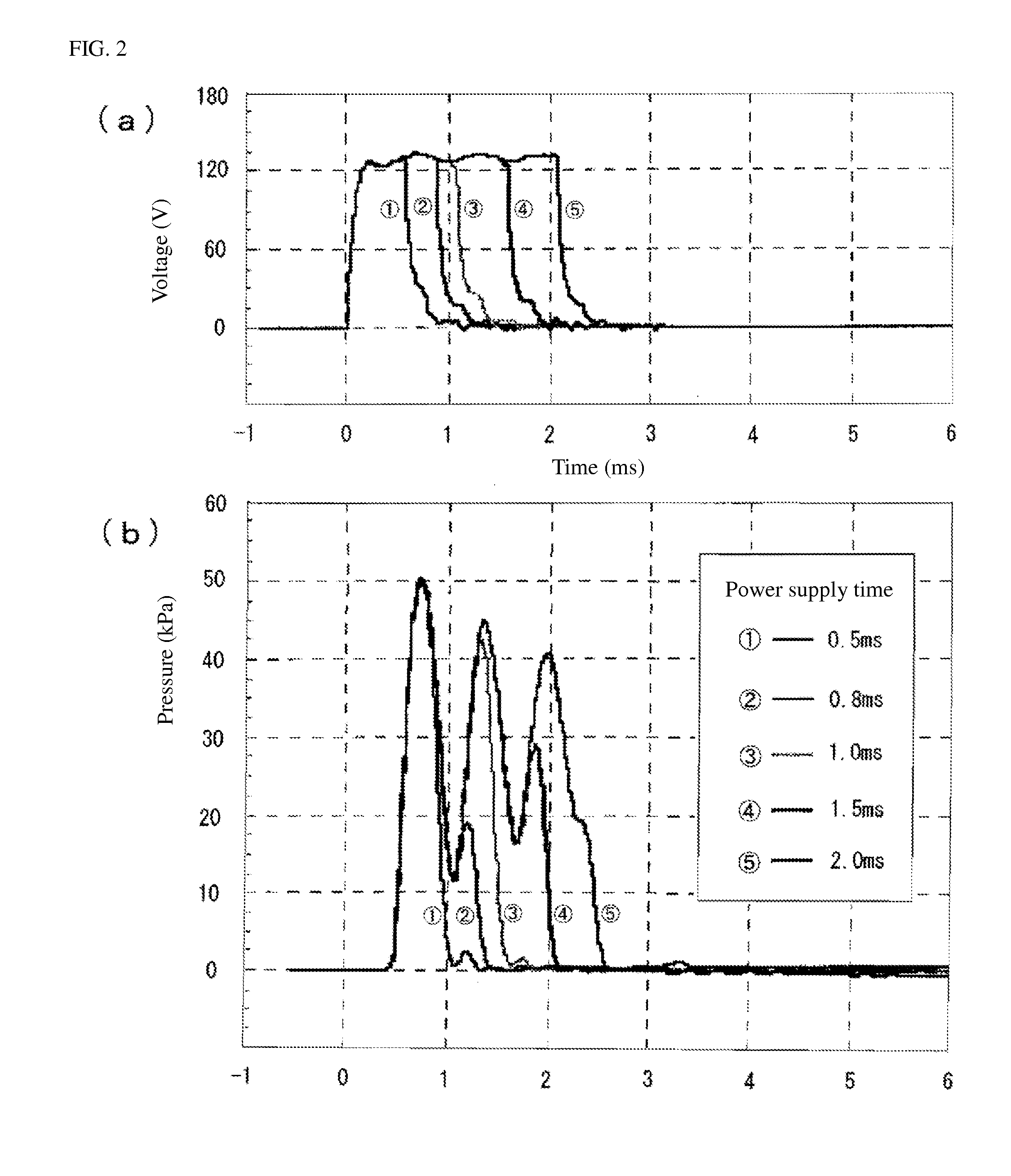
[0081]FIG. 3 shows an example of the voltage waveform applied, under the present invention, to the piezoelectric element 93 from the drive unit 94 when the piezoelectric valve opens.

[0082]As shown in FIG. 3, a first-stage voltage V1 is applied first to the piezoelectric element 93 in a manner allowing an ample amount of gas to be ejected from the gas release channel 912, to drive the valve body 92 to open the valve. Thereafter at a timing to suppress fluctuation in the ejection amount of gas, or specifically at a timing to prevent the valve body 92 from vibrating due to reaction to the valve opening (after an elapse of time t1 following the application of first-stage voltage V1), a second-stage voltage V2 which is greater than the first-stage voltage V1 is applied for the purpose of maintaining the aforementioned ejection amount of gas, and this condition is maintained for the duration of time t2.

[0083]Once the gas ejection time (t1+t2) elapses, the valve body 92 is driven to close ...


PUM


Abstract

A piezoelectric valve comprising: a valve main body formed in which are a gas pressure chamber that takes in compressed gas supplied from the outside as well as a gas release channel through which the compressed gas is released from the gas pressure chamber; a valve body placed in the gas pressure chamber to open and close the gas release channel; a piezoelectric element that generates, in the form of displacement, a driving force needed to operate the valve body; at least one displacement amplification mechanism that amplifies a displacement of the piezoelectric element and causes it to act upon the valve body; and a driving means for applying voltage to the piezoelectric element in order to drive the valve body to open the valve and thereby open the gas release channel; wherein such piezoelectric valve is characterized in that the driving means applies voltage to the piezoelectric element in multiple stages so as to suppress fluctuation in the amount of gas ejected from the gas release channel when the valve opens.

Description

BACKGROUND OF THE INVENTION[0001]1. Field of the Invention[0002]The present invention relates to a piezoelectric valve opened or closed by means of displacement of a piezoelectric element, as well as an optical granular material-sorting apparatus that utilizes such piezoelectric valve and that sorts granular materials by blowing away defective materials, etc., with a blast.[0003]2. Description of the Related Art[0004]Optical granular material-sorting apparatuses have traditionally been known where grain kernels, resin pellets and other granular materials are sorted into good materials and defective materials by blowing away defective materials by a blast, or foreign objects, etc., that have mixed into granular materials are removed with a blast.[0005]Granular material-sorting apparatuses of this type are designed to sort granular material as it drops from an end of a transfer channel along a specified path, by blowing away and removing defective materials, etc., based on defective m...

Claims


Application Information

Patent Timeline
Patent Type & Authority Applications(United States)
IPC IPC(8): F16K31/02B07B4/02B07C5/342
CPCB07C5/3422B07C5/3425B07C5/365Y10S209/938B07B4/02B07C5/366F16K31/004
Inventor ITO, TAKAFUMITAKEUCHI, TERUHIKOYANO, TAKESHICHEE, SZE KEATHIGUCHI, TOSHIRO
Owner SATAKE CORP
Why Eureka
Try Eureka